Encoders8
was developed as an optional addon to the TxrAVR module.
TxrAVR-Picastar's minimum user interface is a 4x3 keypad, four other push buttons,
the main tuning rotary encoder and a 24 or 30 pulse per rev 'menu encoder'.
An early intended option was to control menu-specified parameters with 0-5v
potentiometers connected to ADC inputs. This has the disadvantage that the pot
setting will be applied as soon as it is assigned to a parameter. Incremental
adjustment by rotary encoders is preferrable because the current stored setting
doesn't change until the encoder is rotated.
For many months now, low resolution rotary encoders have been available on eBay at a cost of 0.80ukp each (on eBay). These are the of type used for car radio volume controls, etc. Hopefully such low cost purchases will continue to be available.
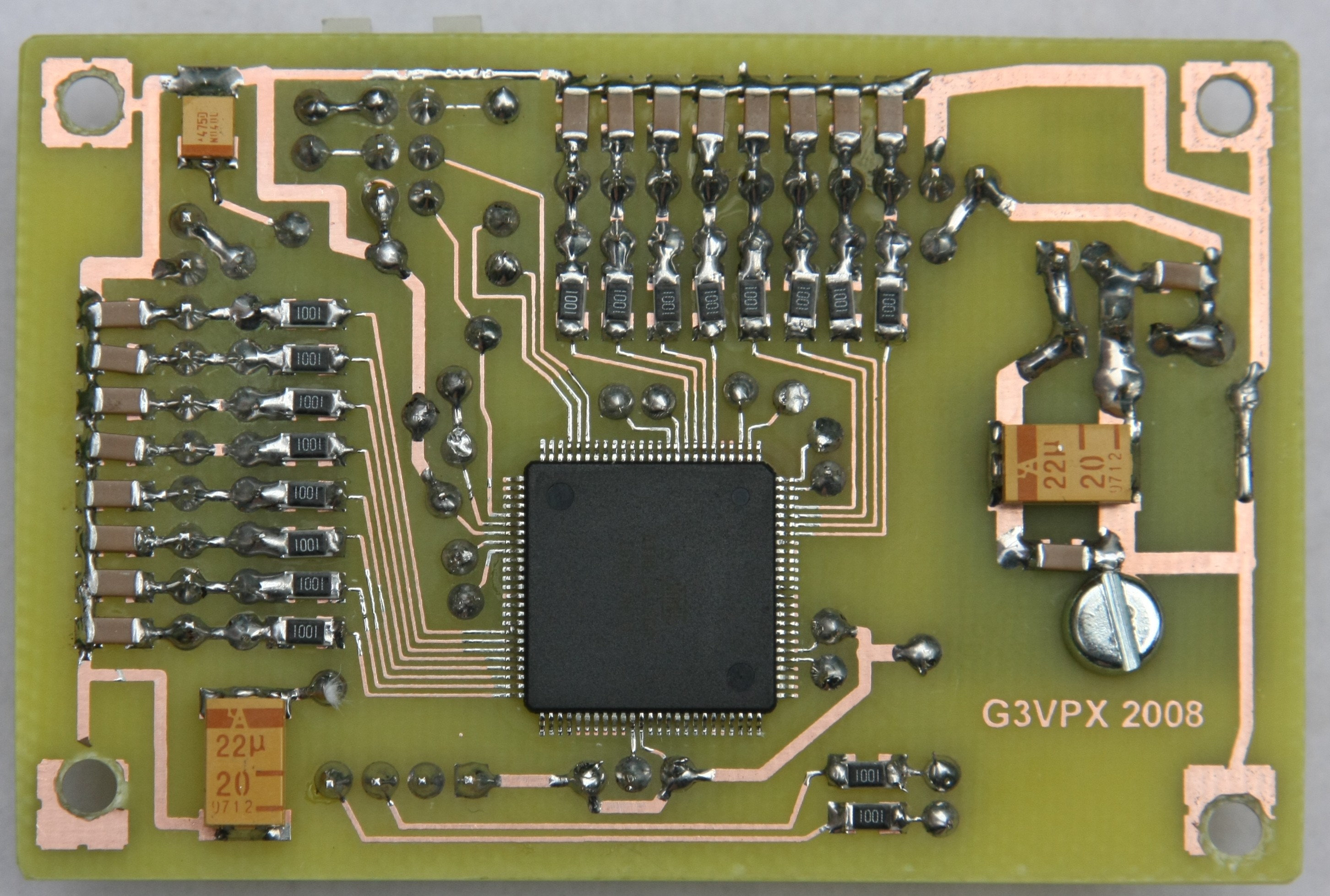
The two rotary encoder inputs to TxrAVR each use a dedicated edge-triggered interrupt. A scan through the available 8-bit AVR chips seemed to reveal that only the larger chips (Atmega1280 and ATmega 2560) have as many as as eight dedicated interrupt lines. I decided to use the 100 pin ATmega2560. In someways its a bit of an overkill: It has 84 I/O lines and I'm only using 17 (+ programming interface), Its has 256kbyte of flash memeory - and I'm only using 1516 bytes!! But it has interrupts INT0 to INT7 and it can be purchased for 6.80ukp + VAT (if you buy 10) and it's the same chip as in the TxrAVR board.
The coding is simple. Eight interrupt service routines respond to a positive edge on the corresponding encoder 'phase' output. The routine examines the encoder's quad output to determine direction of rotation and increments or decrements a counter variable (initially at zero) . The main program loop examines the eight counter variables. If one is non-zero, it tramsits an appropriate message via the USART0 serial port and zeros the counter.
The messages have the form: $3+01, terminated by CR (ASCII 13). This particular message means encoder 3 increment by one.
Board design data is as follows (PCB files use Pad2Pad free software):
- Schematic PDF file
- Layout PDF file
- Schematic PCB file
- Layout PCB file - to print top and bottom copper, enable only the wanted layer and colour it black.
Source and hex code:

The ATmega2560's internal (20k-50k) pull-up resistors appear to be adequate.
(Apologies for the pock-marked copper .. not one of my better etchings - but electrically perfectly ok and solders ok.!)
Each 10-way connector supports four encoders. Bottom right is the serial port.
The six-pin boxed connector is a standard Atmel programming connector.