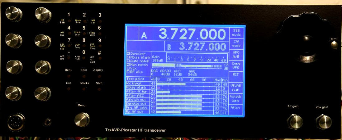
Completed front panel Dimensions are 130 x 330 mm
This panel will soon be on front of a box. See: box design PDF
320x240 graphics display hardware photos
These are from my development rig which uses the following display.
EA W320B-8K3CTP white on blue
See: Displays
Completed
front panel Dimensions are 130 x 330 mm
This panel will soon be on front of a box. See: box
design PDF
This is made from doubled sided PCB. The
rest of the case will also be double sided PCB.
It contains:
Please note that the minumum configuration for TrxAVR-Picastar is:

The front of
my breadboard rig with the completed front panel.
(Ian, G3VPX)
At the bottom is the 40x2 Optrex character display. For development purpose,
TrxAVR-Picastar can simultaneously support
a NT3881 character display and one graphics display option. (Needs alternative
control lines for the character display)
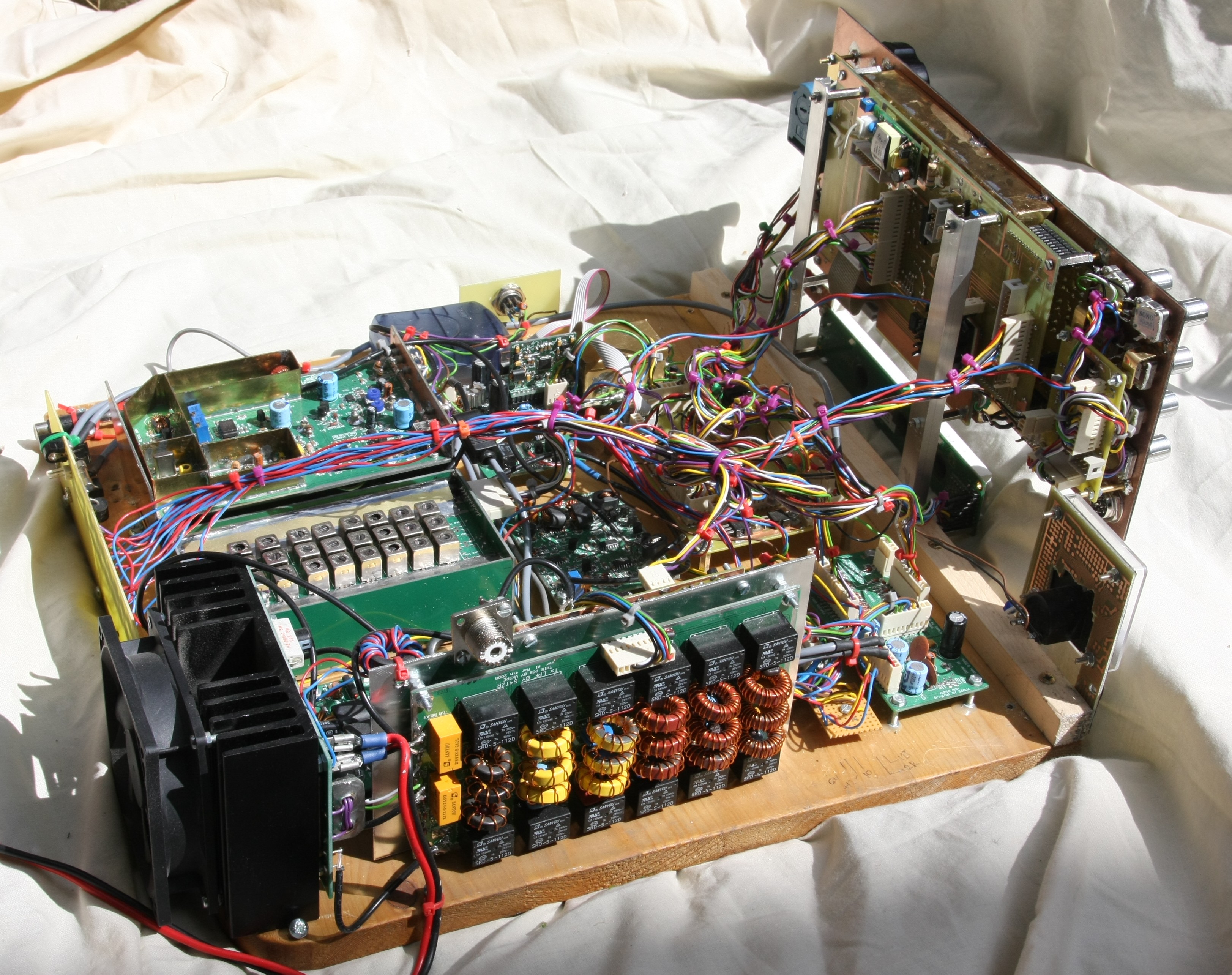
Side view of
the breadboard rig. This
is built using Glenn's Picastar boards.
TrxAVR-Picastar replaces PicNmix. The rest is Picastar technology.
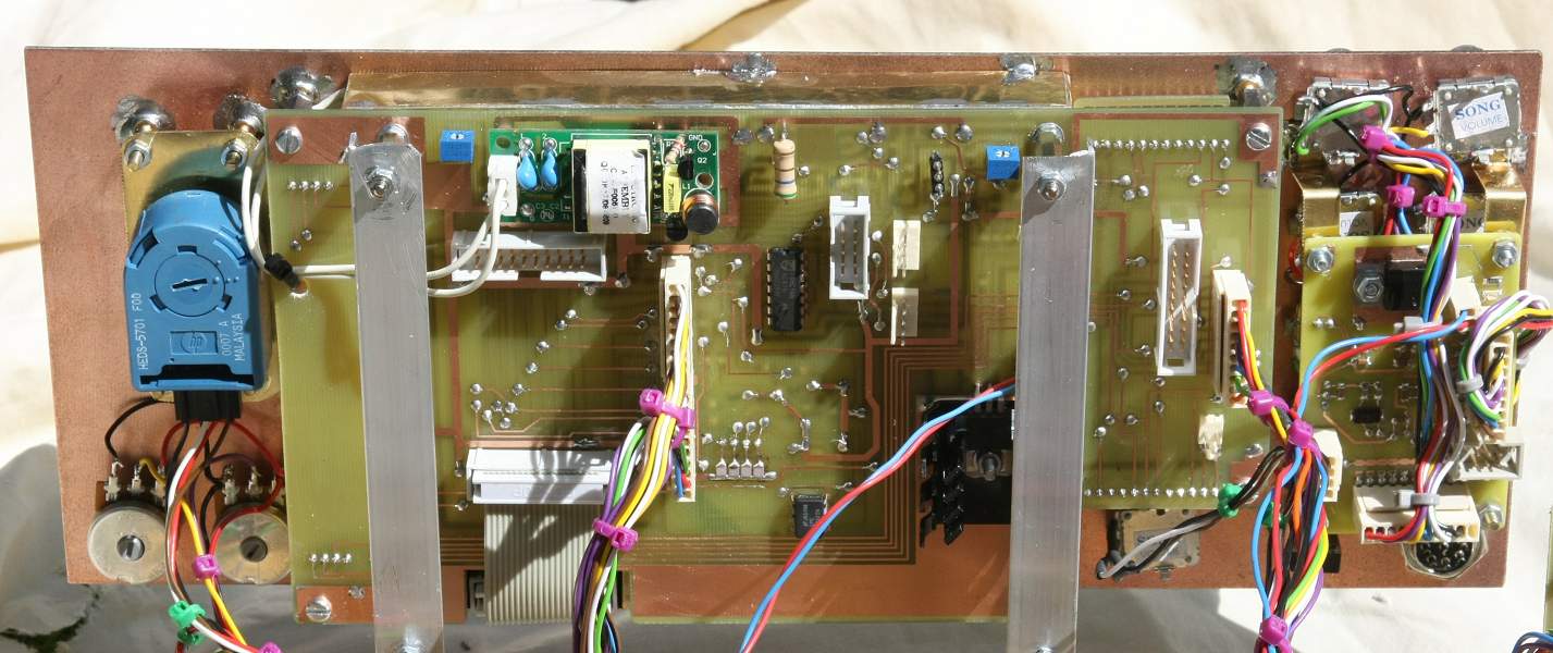
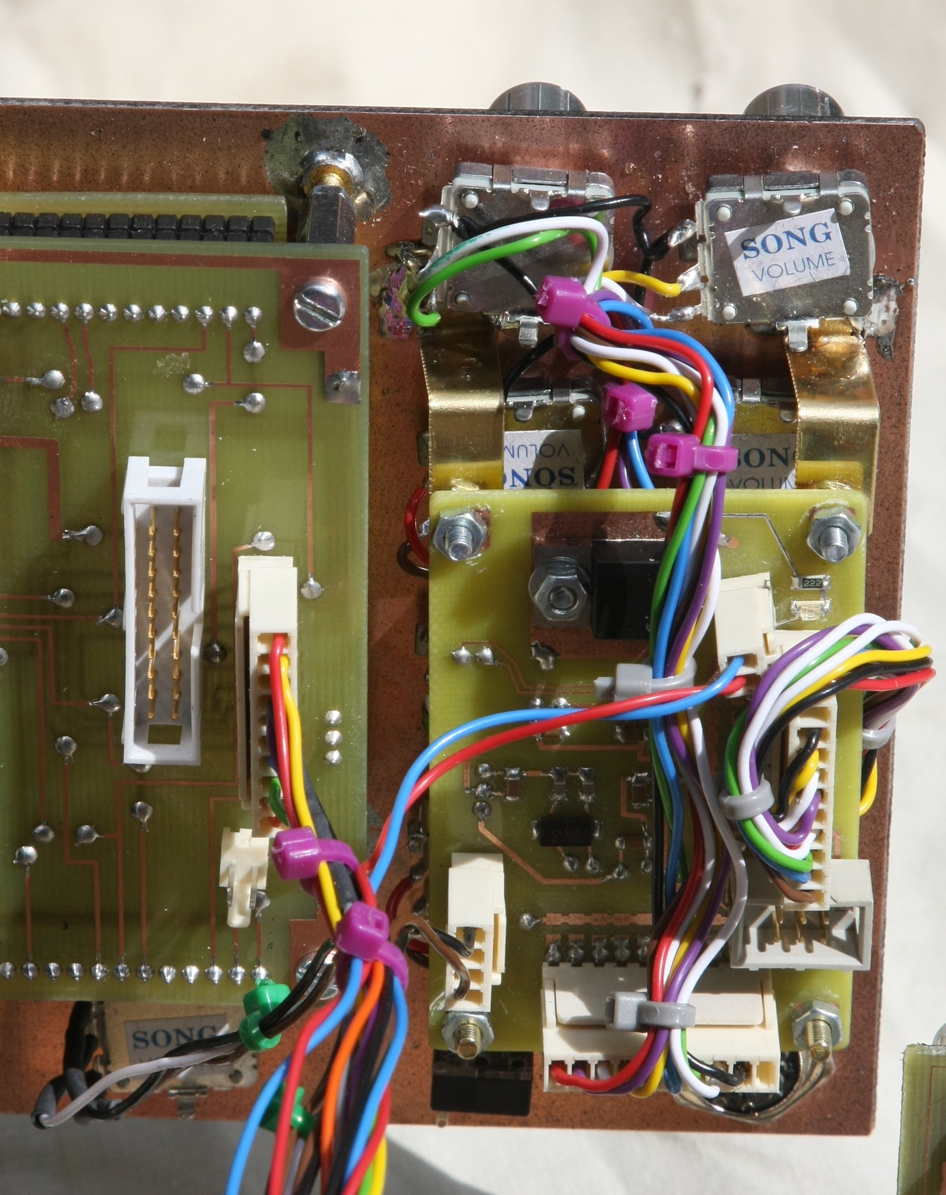
Rear of EA320-motherboard
For a description of the motherboard's fucntion see : Displays
At the top is the inverter for the CFL (fluorescent) display illumination.
The unsed IDC connectors are for TrxAVR-B. (I am using TrxAVR-A)
Front of Motherboard/Display
unit
This has the vertical strip of eight soft buttons on the right.
I removed these as I have touch panel.
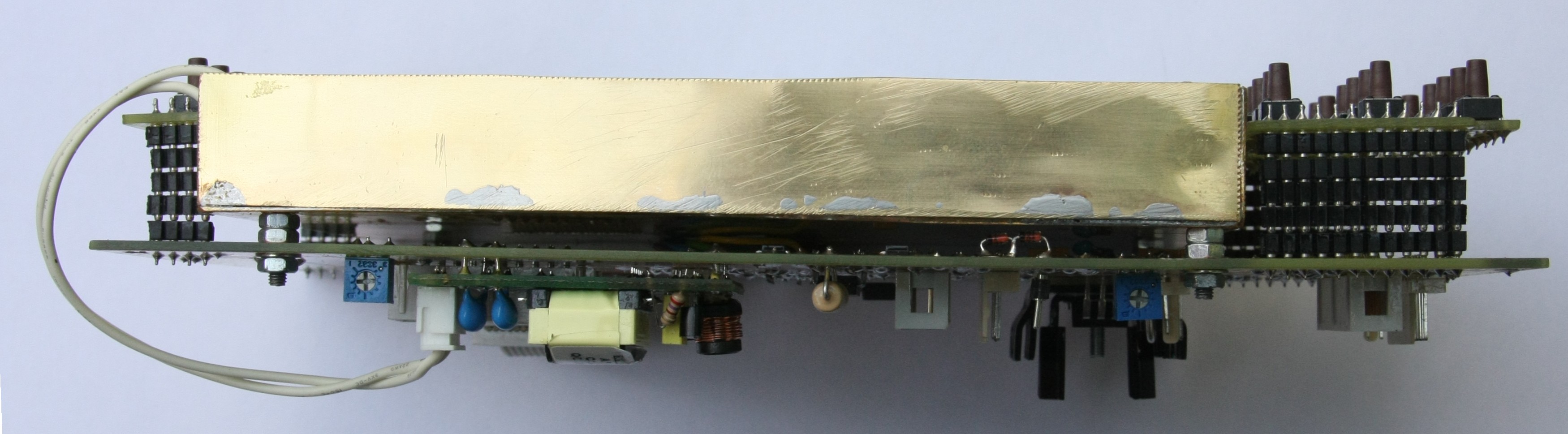
Top view of motherboard/display
assembly
Initially, there was timebase
interference from the EA display board.
This was completely cured by a thin brass shield between display board and motherboard
(in the mounting pillars)
I went further and added brass sides - but probably not needed ... maybe I like
soldering brass.
If the display is in a front compartment seperate from the RF circuits, then
the brass shield may not be needed.
(I will not be able to answer this question because I'm not going to take it
all to bits to find out!!)
Note the stacked, turned-pin SIL sockets to bring the button boards to front panel level.
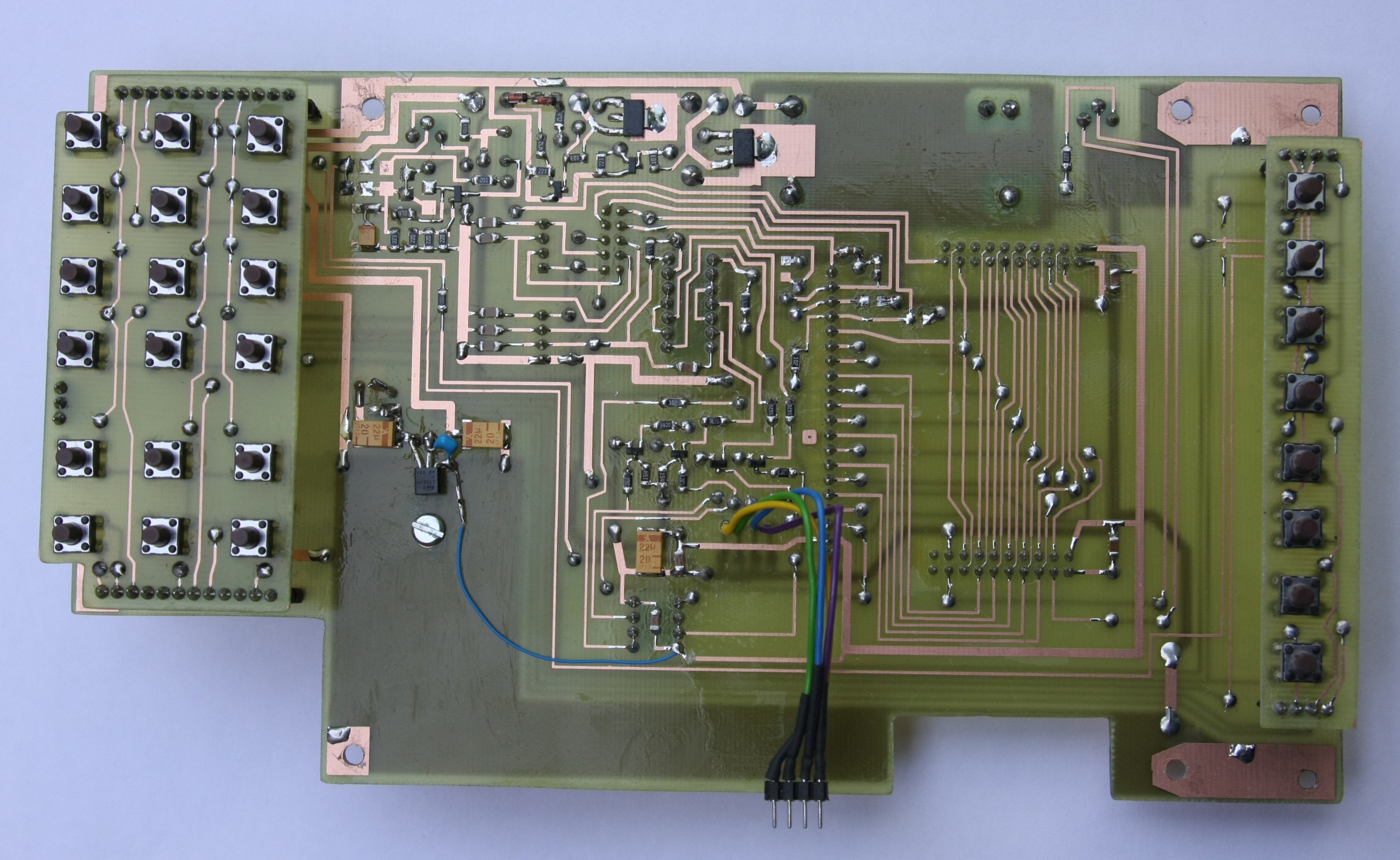
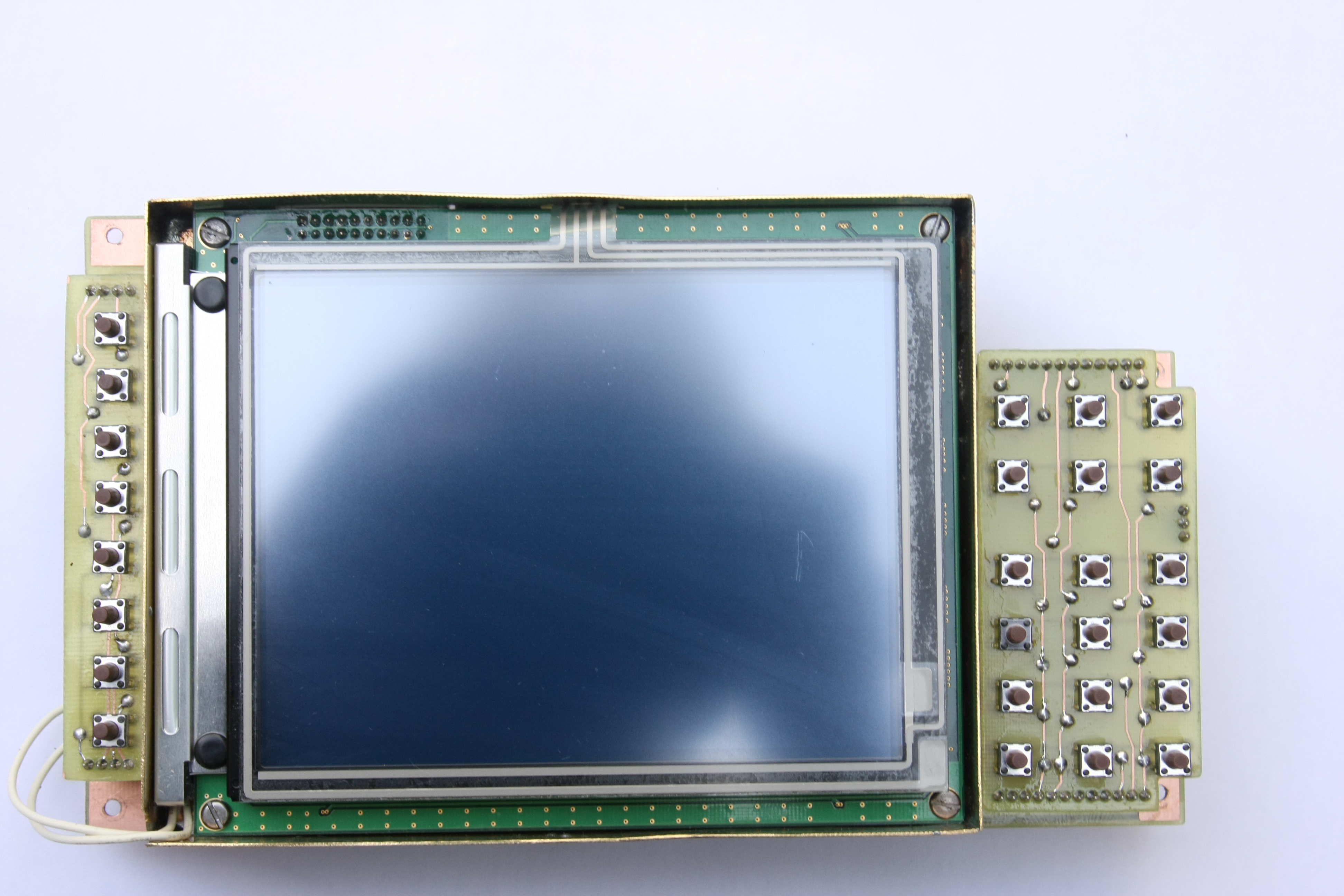
Motherboard - front view with display removed
The cutout is for the display IDC cable. The four-way flying lead connects to
the rather short touch panel ribbon cable.
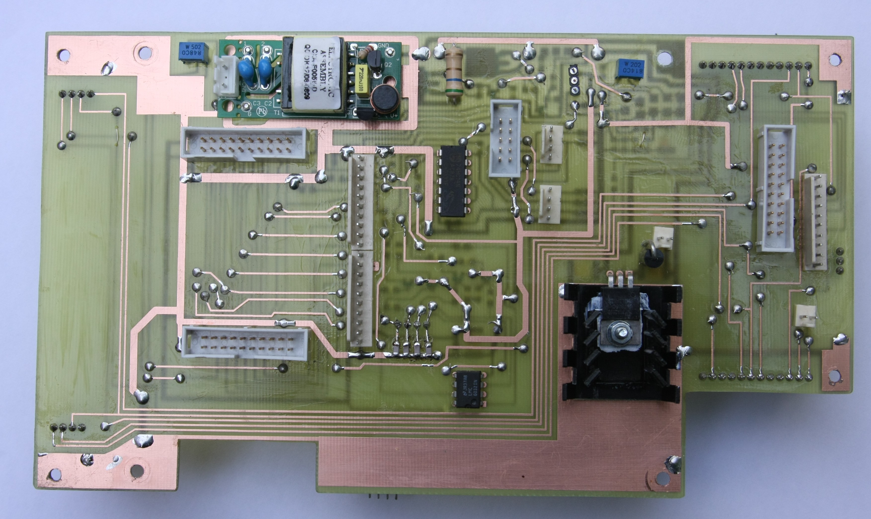
Motherbaord - rear view with display removed.
The EA CFL inverter is at the top. The large heat sink is for the 5v supply
to the inverter. The 7805s on TrxAVR-A do not have
heatsinks. These are ok with the LED display (190mA) but heatsinking is inadequate
for the 410mA needed by the CFL inverter.
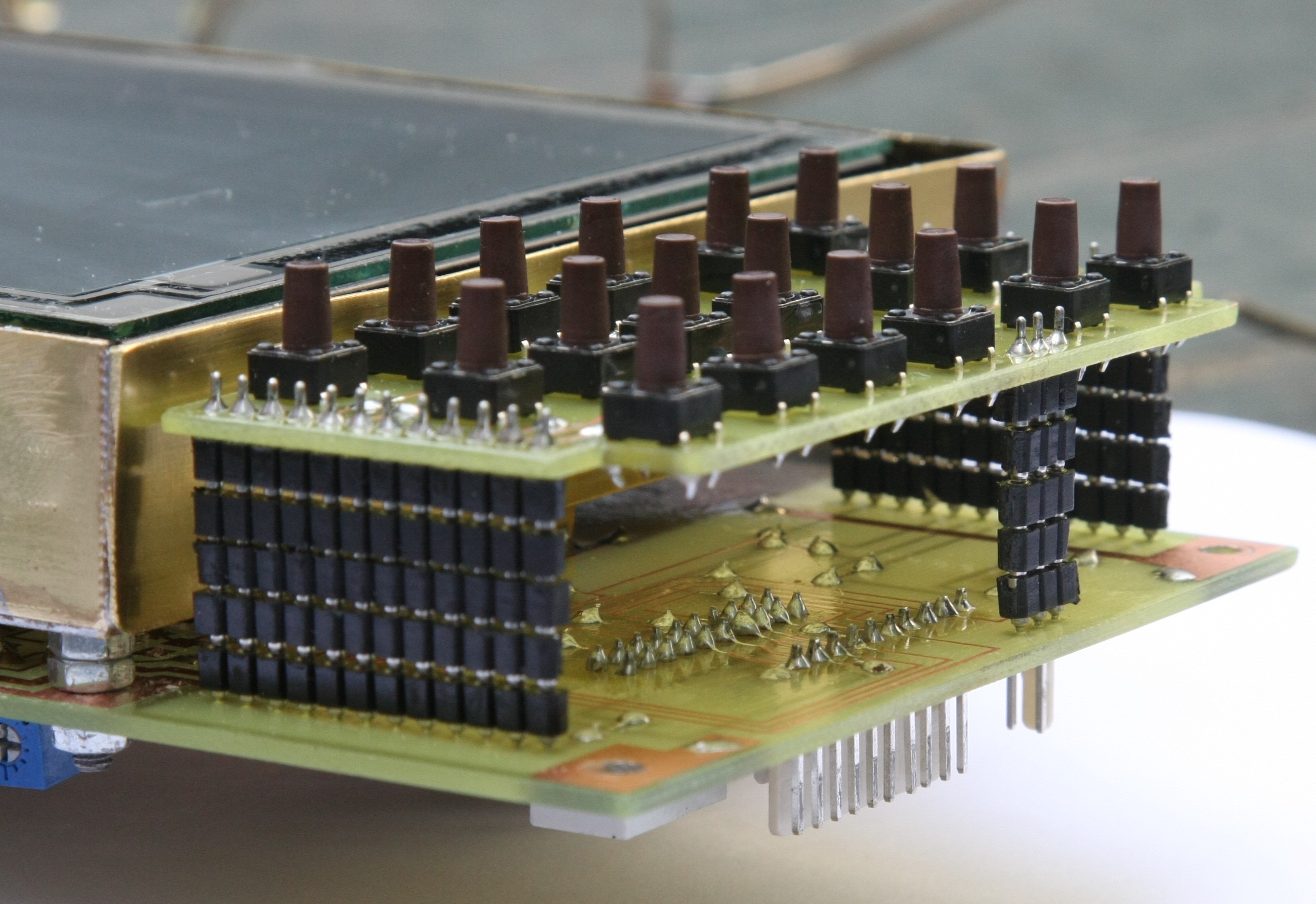
Detail view of button board mounting
Encoders8 board mounted behind the 8 encoders