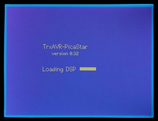
Startup screen. DSP code loads from 24LC512 EEPROM to DSP in 20 seconds
320x240 mono-graphics screenshots
These images are of G3VPX's development rig.
The display panel is
: EA W320B-8K3CTP from Electronic Assembly
see Character and graphics display
The camera doesn't quite do justice to this display. It is brighter and sharper than seen here.
Startup screen. DSP
code loads from 24LC512 EEPROM to DSP in 20 seconds
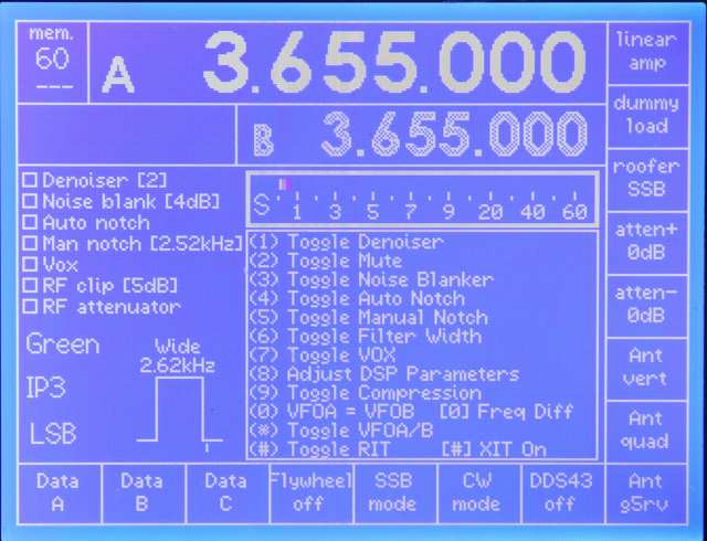
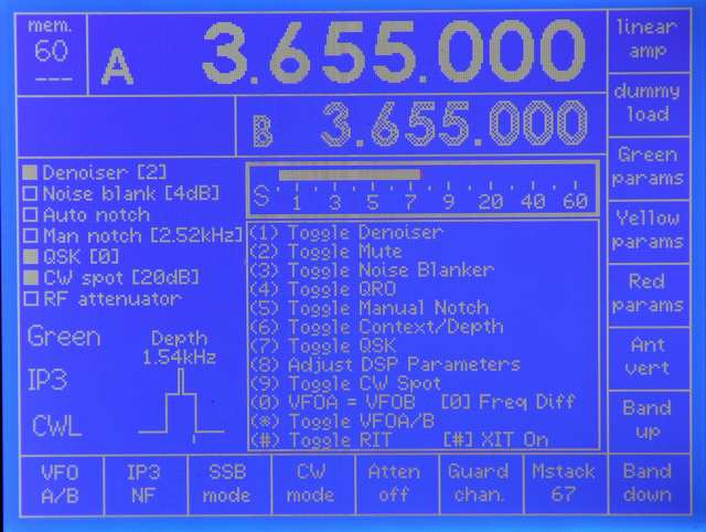
Initial 'home' screen on receive.
This is a touch-screen
with fifteen user-assigned touch buttons, right and bottom.
If no touch screen is fitted, then the eight on the right are on-screen labels
for a vertical
strip of eight push buttons. The seven at the bottom are then absent , but their
functions are
accessed by Shift 1 to 7.
The centre of teh screen gives DSP switch help.
Top left is the current Memstack.The --- beneath it indicates thaat no memslot
is selected.
Note the filter width graphic.
This changes in width as the width is adjusted. If you adjust
the narrow setting, the graphic changes to show the narrow setting during the
adjustment.
The small verticl line beneath the filter shape shows the carrier point.
Note the use of white and grey to indicate which VFO is current (white).
![]()
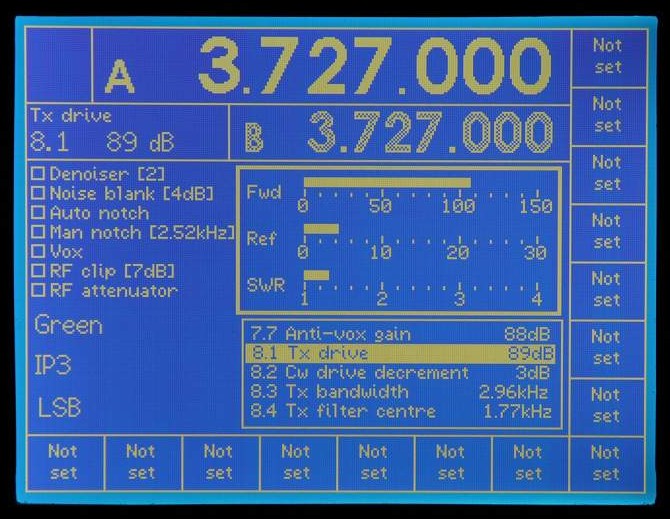
Transmit screen.
The user-assigned buttons are assigned separately for transmit and receive.
The transmit buttons have not yet been assigned here.
At the bottom is numeric DSP monitor information.
The Display button toggles between:
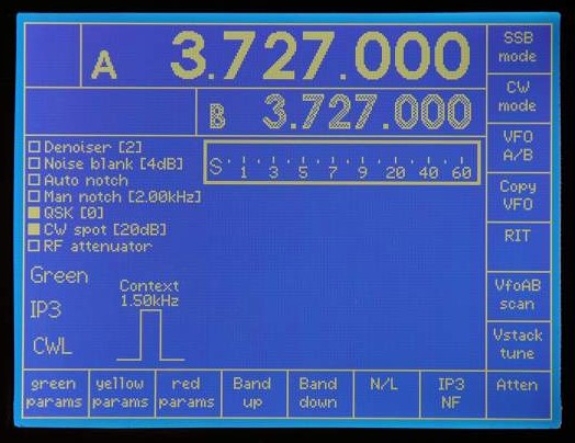
CW mode. Indicated by CWL.
Note switch labels and data have changed for CW.
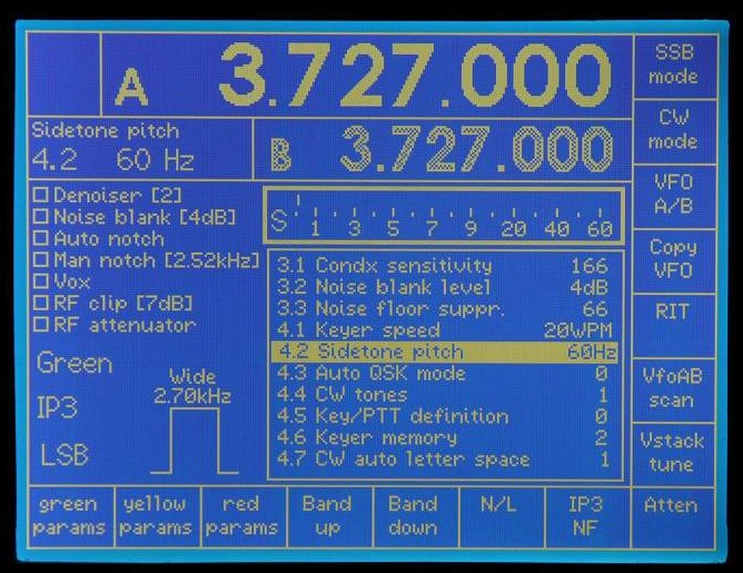
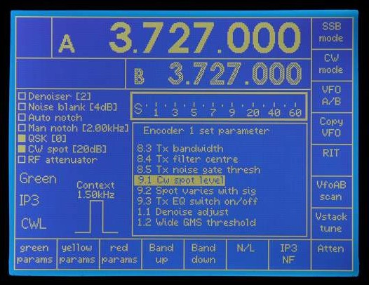
Setting DSP parameters.
This is accessed from the 'home' state either
by:
Setting DSP parameters
on transmit
The process is the same as on receive with a smaller menu / message window.
Showing filter graphic on CW with
filter switch set to Depth
The graphically indicated filter depth changes
to indicate depth ( 0 - 90dB)
Also note the check boxes for switch indication
and the associated numeric data.
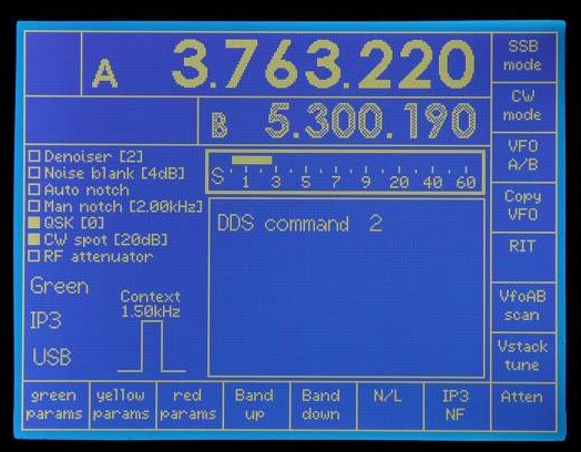
DDS command: A long press of the 2 key opens the
message window.
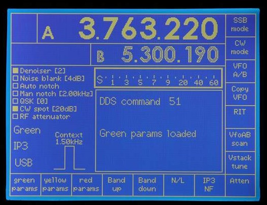
DDS command: 51 keyed.
A transient message indicates the effect of DDS51.
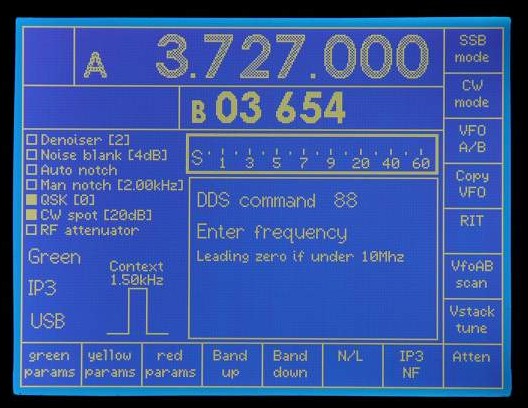
DDS 88 keyed (manual frequency entry).
Seven digits - so freq. entered to 10Hz.
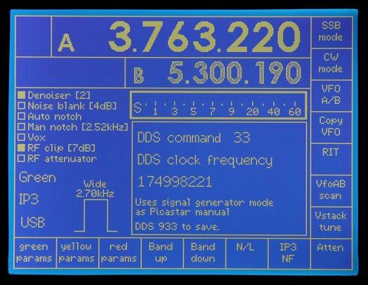
DDS33 keyed (setting
DDS clock). Operates as
Picastar manual except no reboot.
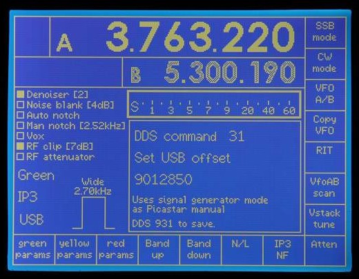
DDS31 keyed (setting
USB offset). Operates as
Picastar manual except no reboot.
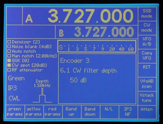
Encoder 3 turned.
This encoder has been assigned to DSP parameter 6.1.
The first encoder click displays the message window showing current parameter
value.
Subsequent encoder clicks adjust the value. The graphic and value indication
change on each click.
The message window disappears 2 seconds after no encoder 3 activity, but if
another encoder
is turned, the message switches to it immediately.
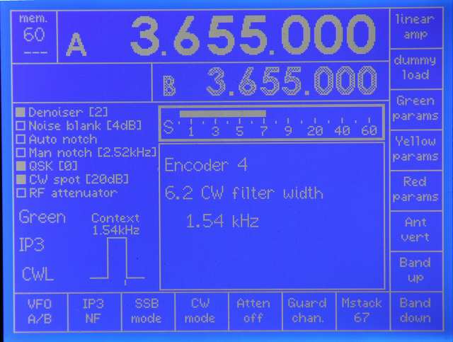
Encoder 4turned. This encoder
hase been assigned to DSP parameter 6.2, CW filter width.
The filter graphics changes as the adjustment is made.
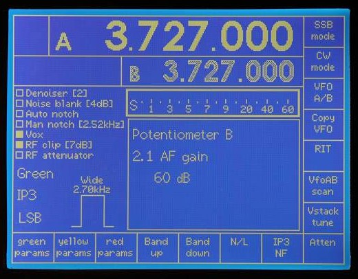
Potentiometer B turned. This pot
has been assigned to DSP parameter 2.1, AF gain.
Potentiometers A aand B are
of limited use because they define an absolute level rather
than being incremental like the encoders. Hovever, their use
for AF gain, Vox gain etc
is appropriate. (For AF gain the pot will control a range
50 to 100dB rather than 0 to 100dB)
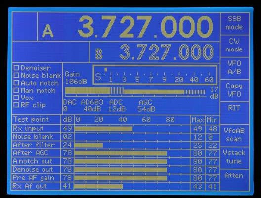
DSP monitor display on receive.
This mimics the DSP display of G3XJP's loader program.
(Note that TrxAVR-Picastar always runs with DSP parrameter 52. set to 2.)
The lower seven touch buttons are overwritten but can be accessed by Shift 1
to 7.
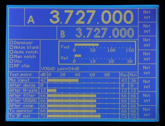
DSP monitor display on transmit.
Power meter is reduced to Fwd and Refl with no SWR.
Drop in menu over DSP monitor.
Message windows behave likewise.
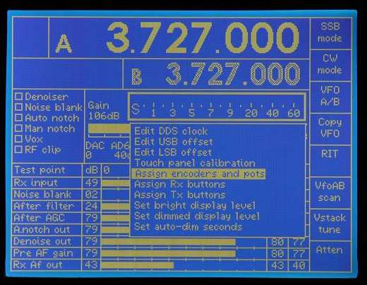
This is the configuration menu, accessed by the menu
key.
All menus and lists are scrolling/rotating with a fixed central highlight bar.
Press menu key again to select.
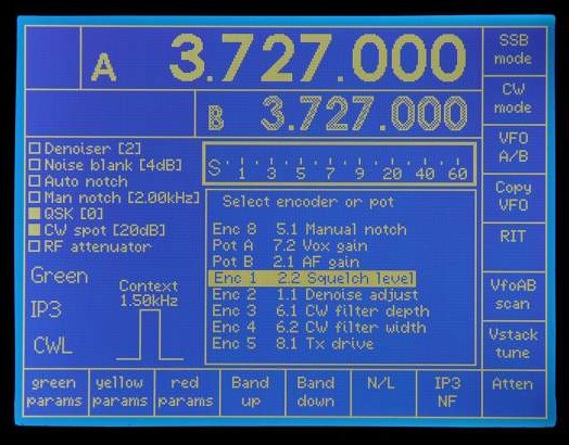
Assign encoders and pots sub-menu.
This allows assignment of a DSP parameter to each of eight encoders and two
pots.
Assigning
a DSP parameter to Encoder 1.
The parameter list excludes parameters fixed in September 2208 by G3XJP (x prefixed)
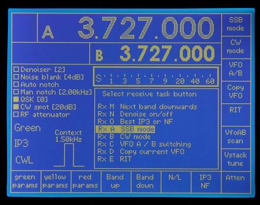
Selecting a receive button for task assignment
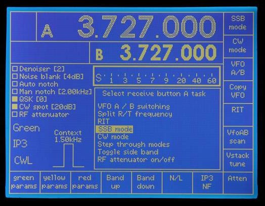
Assigning a task to receive button A
There are 50 or so available tasks (DDS, DSP and other)
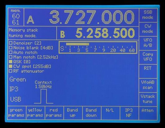
Memory stack tuning mode (from DDS 60).
Top left. The stack number, 60 remains fixed, The slot number changes from slot
61 to 66.
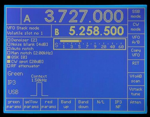
VFO stack tuning mode (from DDS 27)
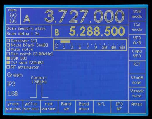
Scanning current memeory stack (60) (from DDS56)
Note this is happening on VFO B which was current.
Scan delay is set by tuning encoder as in Picastar.
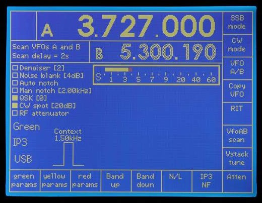
VFO A and B scanning (DDS5*)
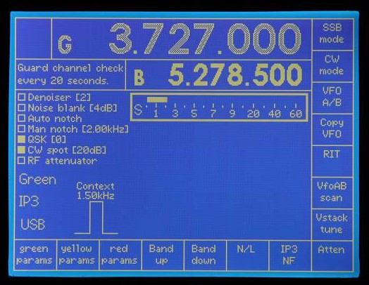
Guard channel monitoring. VFO
B is current so VFO A is guard channel labelled 'G'.
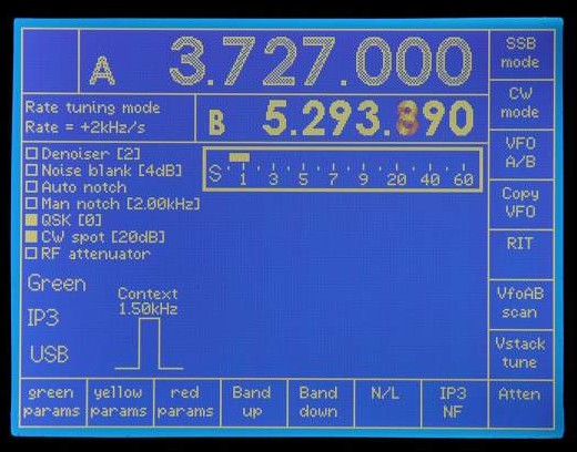
Rate tuning mode (DDS22). Tuning
encoder sets rate as specified in Picastar manual.
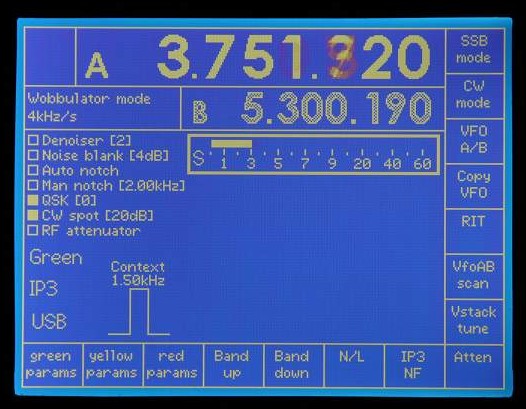
Wobbulator mode. (DDS58). Tuning
encoder sets sweep rate as in Picastar.
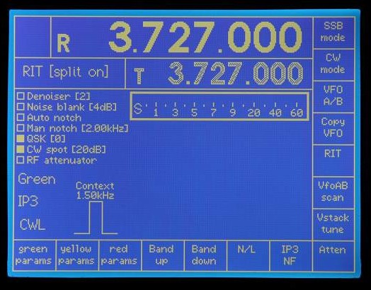
RIT mode - split on. # key behaviour
is exactly as Picastar.
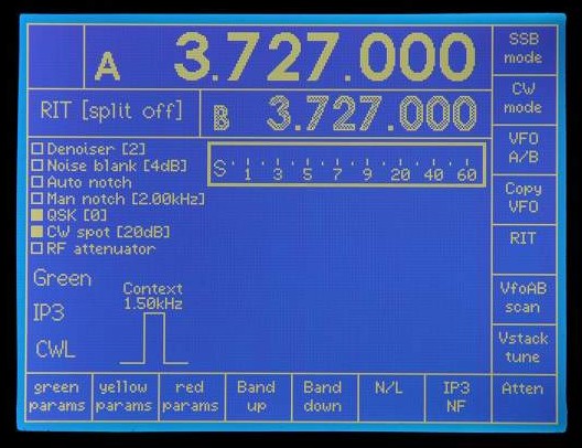
RIT mode - split 0ff. # key behaviour
is exactly as Picastar.
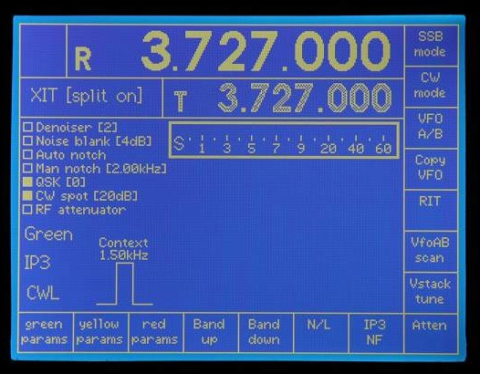
XIT mode - split on. # key behaviour
is exactly as Picastar - except that if you hold
the # key, the transmit display immediately changes to frequency difference.
(In Picastar, this only happens when you tune. This restriction is unneceassry
here as
we have two VFO displays)
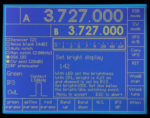
Configuration menu - Setting bright display level.
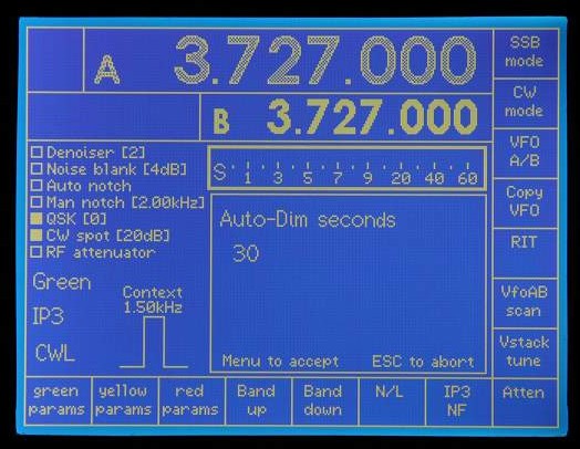
Configuration menu - Setting Auto-dim seconds
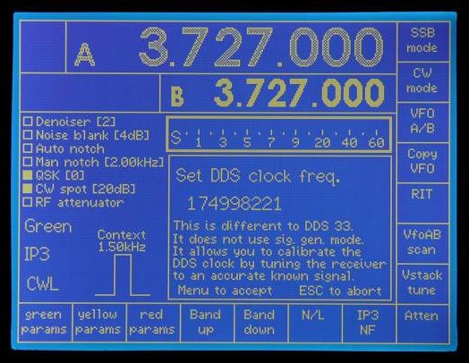
Configuration menu -Setting DDS clock
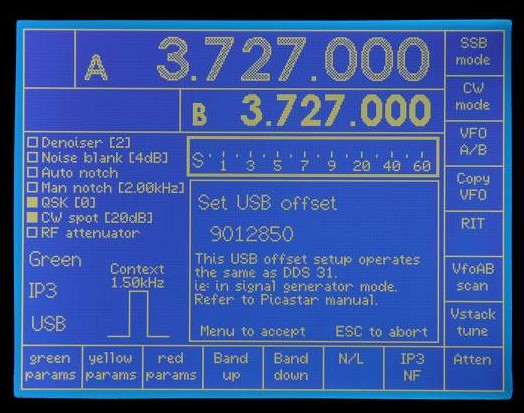
Configuration menu - Setting USB offset
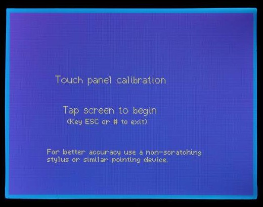
Configuration menu - Touch panel calibration
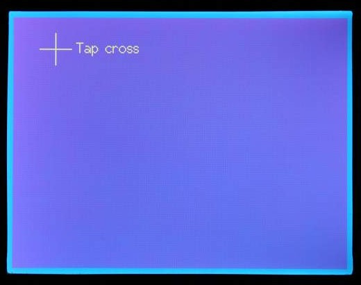
Touch panel calibration is by chaseing a moving
cross.
Firm steady pressuse with a non scratching stylus is needed as the software
insists on
six consequetive identical XY readings. This slightly tricky procedure results
in a
touch screen resolution of 2 pixels which is more than adequate for the 30x40
pixel
touch buttons.