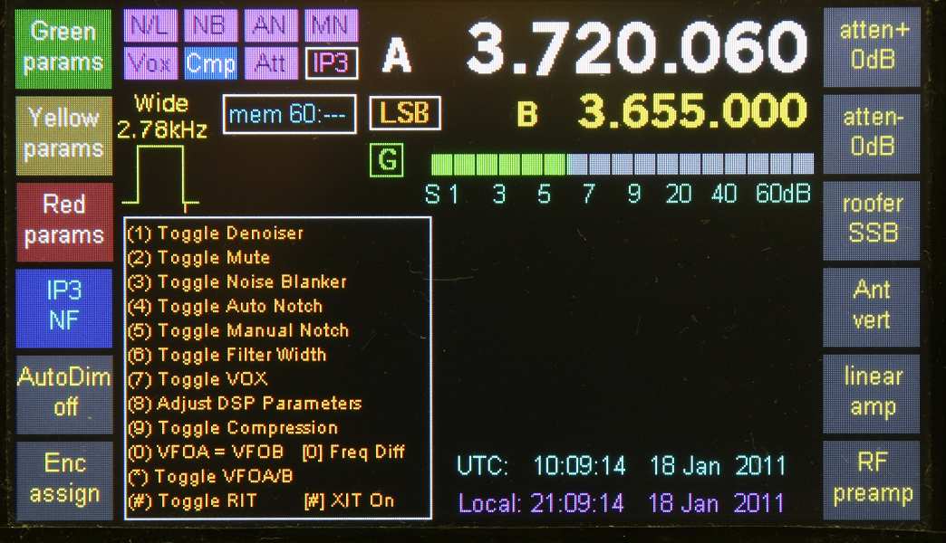
TrxAVR TftA display with Real Time Clock - Melbourne time offset
The RTC display is not visible during param setting, transient DDS messages, when menus are displayed
and when the DSP monitor display is selected.
TrxAVR_Picastar - Real Time Clock (RTC)
Please also read: User Signature Row and TftA I2C address configuration
Link to RTC web page of Glenn, VK3PE : http://www.carnut.info/Trx-RTC/RTC.htm
Comparison of 5 RTC devices: Compare RTCs
RTC support requires: Hobcat 1.078 TrxAVR 1.67 TftA 2.25 or later.
TrxAVR now supports a real time clock:
RTC display screen images:
TrxAVR TftA display with Real Time Clock
- Melbourne time offset
The RTC display is not visible during param setting, transient DDS messages,
when menus are displayed
and when the DSP monitor display is selected.
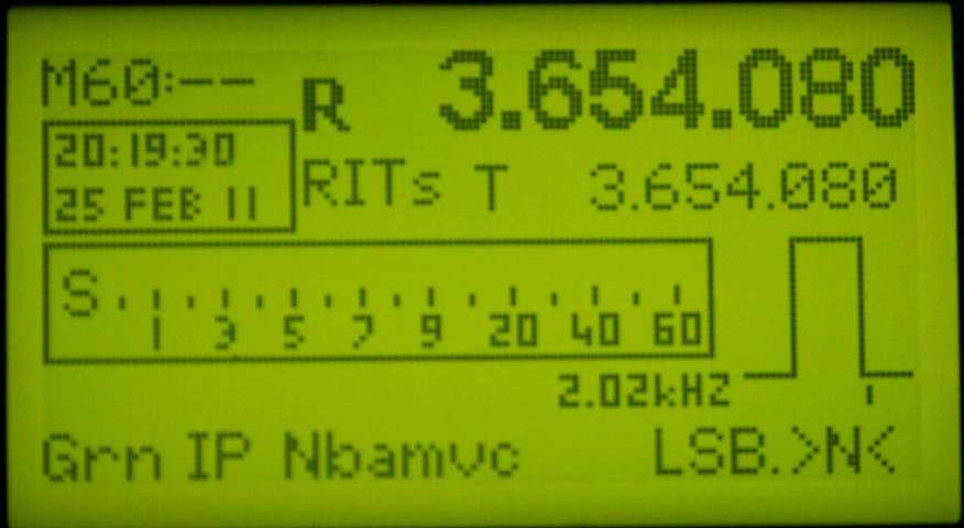
128x64 mono
graphics
Screen space is very limited here and so only local time is displayed.
You can opt to display UTC by setting the Local Time Offset to zero.
320x240 mono graphics
With 320x240 mono graphics,
it was more difficult to find a position for the RTC display.
There are therefore three positions, one of which is automatically selected
according
to screen configutation settings:
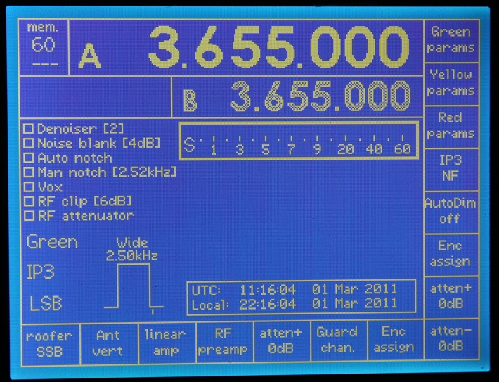
320x240 mono graphics - RTC display at bottom of screen (RTCpos = 1)
(Only
if no touch pad or bottom button labels)
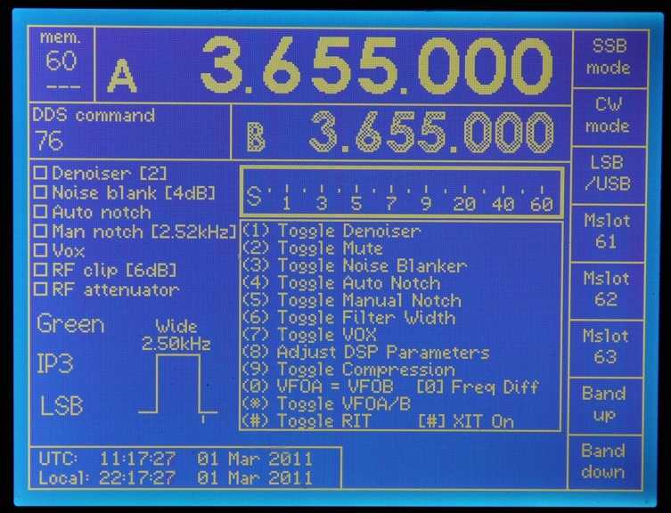
320x240 mono graphics
- RTC display in menu area (RTCpos = 2)
Used
if no DSPkey help (DDS76 option).
RTC termporarily hidden by menus and messages.
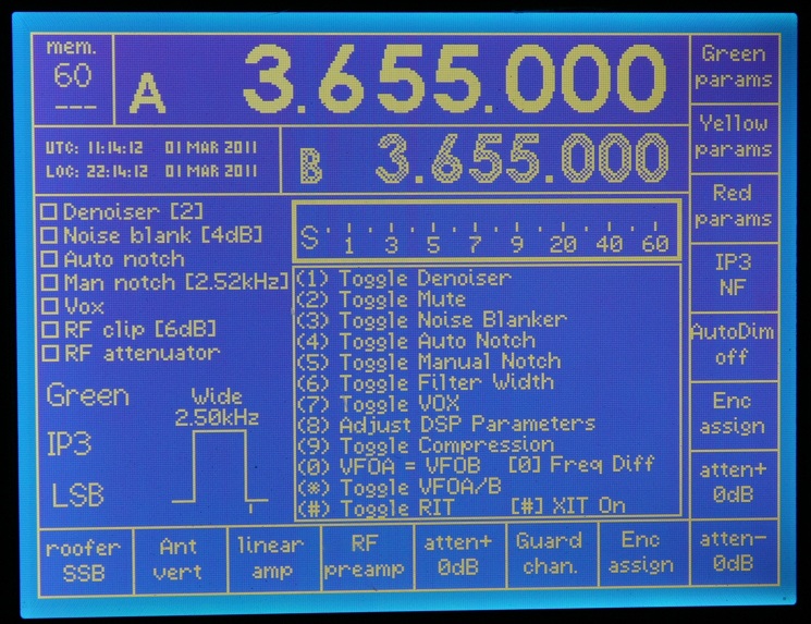
320x240 mono graphics -
RTC display upper left (RTCpos = 3
Used
if DSPkey help slected (DDS76
option).
Samll (5x3) font used.
RTC temporarily hidden by param setting
and some traansient message.
RTC not visible in modes: RIT, XIT, VFO stack tune, mem stack tune, wobbulator,
scanning.
If you
need the RTC with XIT or RIT split operation, then use DDS76 to switch off
DSPkey help - so as to display RTC in the menu area (RTCpos =2).
Supported RTCs
The five RTC chips are:
G3VPX's Five-RTCs
on a PCB
Only three devices can be active on the I2C bus at any time.
This is because the DS3231 and DS3232 both have address = 0x68
and PCF8563 and RTC-8564 have both have address 0x51 - hence the device selection
jumpers.
This is essentially a development / evaluation board
But if anyone wants make one, see: layout
schematic top
mask bottom
mask (or email me for Pad2Pad files)
For a comparison of the five chips see: Compare RTCs
Please note that we
initially reviewed the DS1307 and PCF8583 assembled PCBs from Futurlec.
These are low cost and excellent ... but these devices cannot be used as their
maximum I2C bus clock speed is 100kHz.
TrxAVR I2C bus runs at the current standard of 400kHz. Communicating with selected
100kHz devices at a lower
speed is not an option, because all devices have to decode all the data in order
to identify their own address.
(The DS1307 caused TrxAVR to freeze during 1 in 4 DSP loads , and otherwise
stopped TrxAVR in 1-3 minutes.)
We haven't identified
any other ready made modules with 400kHz
devices.
Our recommended RTCs:
I have home-brewable PCB designs for these two devices.
Glenn, VK3PE has designs for all five RTC devices. See: http://www.carnut.info/Trx-RTC/RTC.htm
Please
note that the DS3231 is very similar to the DS3232.
It does not have the 240 bytes RAM (which we don't use), and it is in a 16 pin
package.
It is however older and slightly more expensive.
Changes
to TftA I2C address management affecting all TftA systems.
These changes
initially resulted from a clash with the ISL1220 I2C address.
They have resulted in development of Hobcat control of AtXmega128 User Signature
Row which
then lead to the capability of configuring TftA from Hobcat (instead of TftA
jumpers)
The ISL1220 has a fixed I2C address of
0x6F (hexadecimal 6F)
This is the same address that has been used for the TftA colour
display and is the default
address for the EA colour TFT modules with no address links installed.
Earlier TftA and TrxAVR code had the TftA I2C address 0x6F hard coded in the software.
The current software with RTC support has:
These can be set from Hobcat.
Special provision is made to deal with the fact that
Hobcat cannot communicate with
TftA unless the TftA I2C addresses match in TftA and TrxAVR ... and if you can't
communicate
then you can't change the address in TftA !!
Please carefully read the web pages on User Signature Row and TftA I2C address configuration.
eDIPTFT43-ATP display
Prior
to the availability of TftA, a few people purchased a eDIPTFT43-ATP
display.
This has I2C address selection by jumper links. These will need changing to
change the address.
We have suggested using address 0x6B. This is a seven bit address,
ie not including the final R/W bit.
This is selected by grounding pin 10 ( SA2 = slave address 2)
Read the EA manual carefully to understand this:
BA0, BA1 and BA2 all high are translated to give upper byte (of 8 bit address)
= 1101
SA0 and SA1 high and SA2 low directly give lower byte = 011x where x is the
R/W bit.
Combining these: The 8 bit address = 1101 011x.
Shifting this one place to the right to give the '7 bit' address give 0110 1011
= 0x6B.
Clock frequency adjustment
All five RTC devices can
produce a 32kHz output signal
All except the RTC-8564 have a means of frequency trimming.
There are 31,536,000 seconds in a year.
Therefore, a 10 second per year error corresponds to a frequency error of:
32768 / (31536000
/10) = 0.01Hz
In order to adjust to this accuracy using
the 32kHz output, you need a frequency meter that can measure
32kHz to 7 digits or better, ie: 32768.01 Hz.
This needs a very long counting gate period or a very clever
frequency meter.
I (G3VPX) have a oven-controlled HP5385A
counter which has 8 decimal places and which can read low
frequencies to full accuracy using interpolar-enhanced reciprocal
counting. I'm not sure exactly how this works,
but it must involve some use of the measured signal as a gate and some internal
reciprocal mathematics.
It can measure 32768.01Hz with a 1 second or 10 second counting time.
I have used this instrument to adjust and evaluate the RTC devices.
For the
benefit ofbuilders who haven't such an instrument please post your alternative
suggestions
on the homebrew-radios group!!
Without a suitable counter, then the adjustment
can still be done, but much patience will be needed.
Make an adjustment say, every few days or a week, comparing the time with an
accurate source,
until the desired accuracy is achieved
RTC type selection
in Hobcat
Hobcat's Hardware Settings
window now has an RTC selector.
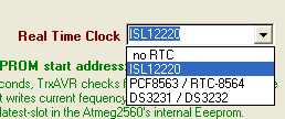
Intersil ISL1220 - I2C address fixed at 0x6F
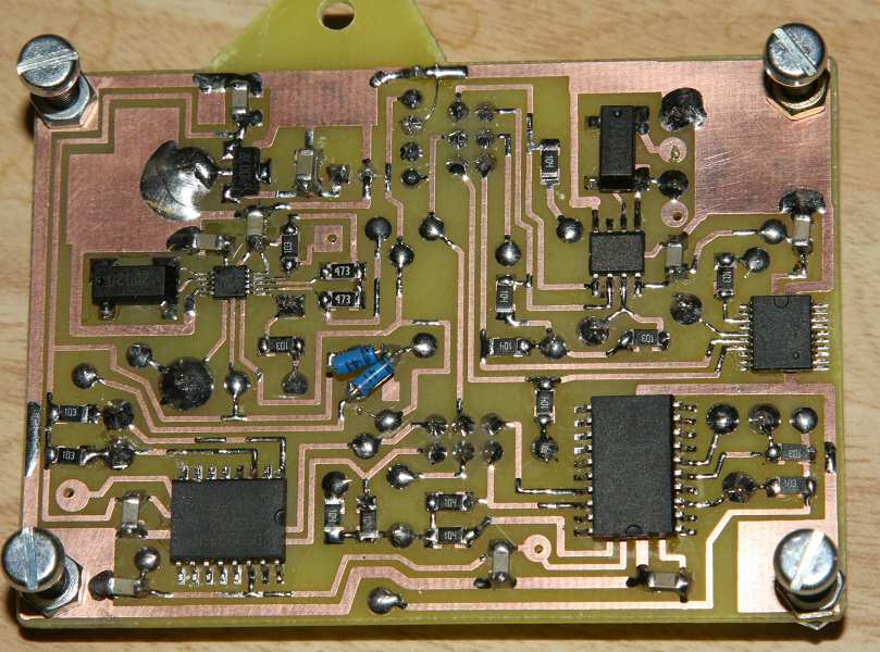
We have designed and tested
a home-brew single sided PCB for the ISL1220.
Links to the files are below. The .pcb files need a download of Pad2Pad (free).
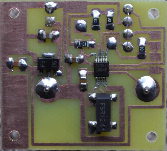
ISL1220 PCB (Paul M1PVC)
Note SMD 32kHz Xtal and SMD 78L05
This PCB has one I2C connector. The current design has two I2C connectors.
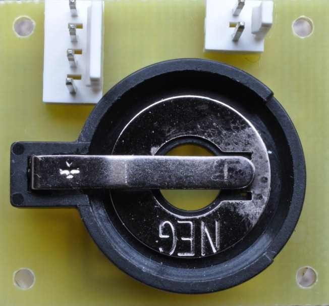
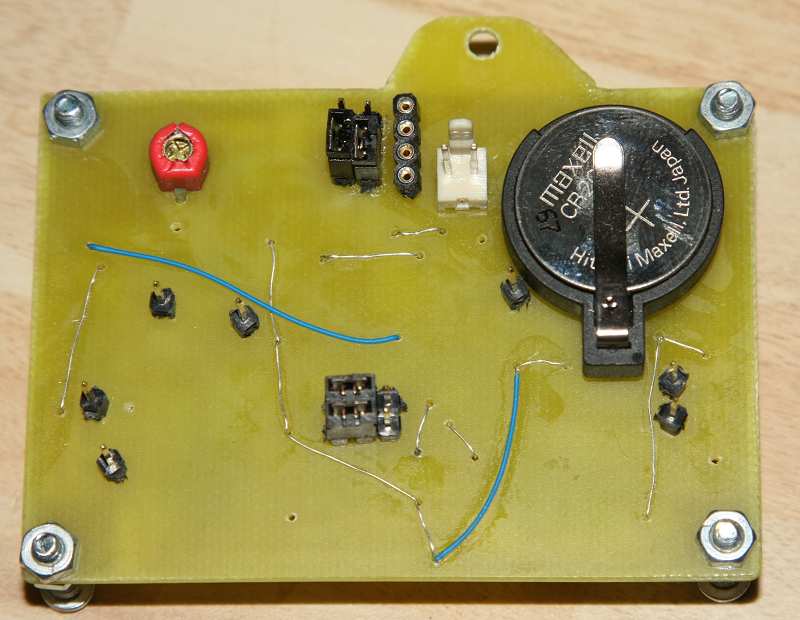
ISL1220 PCB top view - with battery holder for
CR2032
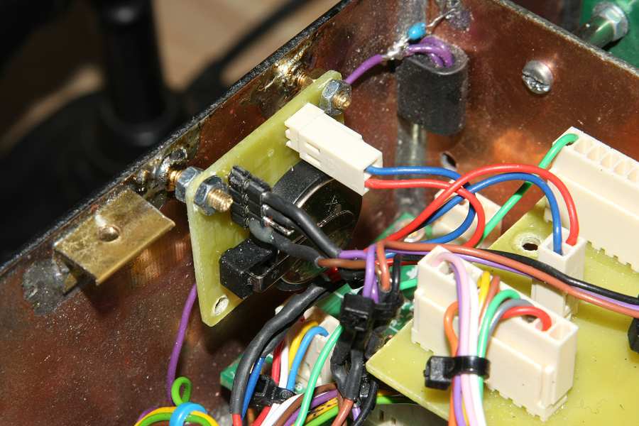
ISL1220 module installed (G3VPX)
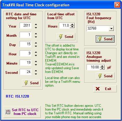
ISL1220 configuration window in
Hobcat.
The date and time setting and local time offset are common to all RTCs.
Frequency out is ISL1220 specific - having the ISL1220 freq. options.
Analogue trimming is specific to ISL1220.
Local time offset has range -12 to +12 hours in 30min (0.5 hour) steps.
When this window opens, date/time, trimming
and Fout settings are read in from the RTC.
The Send buttons send to the RTC. These setting are not stored elsewhere.
Local time offset is stored in the TrxAVR ATmega2560 internal EEPROM and
can be saved from there to TrvAVReemem.ini.
The ISL1220 has 15 Fout options from 0 to 32kHz.
Analogue
Trimming Register (ATR)
The ATR has six bits ATR0 - ATR5. These have a 2s complement trimming value.
The register adjusts the crystal load capacitance between 4.5pf (ATR = 100000
= -32)
and 20.25pf (ATR = 011111 = 31). The capacitance/frequency curve is non-linear.
ATR=0 (default) gives 12.5pF which is the specified load capacitance for most
crystals.
My measurements:
Fout set to 32768 kHz and
fed to my HP 5385A oven-controlled 8 digit counter.
Cload = 4.5pf -> 32770.0Hz = 32768 + 2.0Hz
Cload = 12.5pF -> 32767.7Hz = 32768 - 0.3 Hz
Cload = 20.5pF -> 32766.9Hz = 32768 - 1.1 Hz.
Cload adjusted to 10.75pF
to give Fout = 32768.00 Hz
With the default 12.5 pF (ie no ATR provision) the error was:
60*60*24*365 /( 32768 / 0.3) = 288 seconds/year = 5
minutes per year.
The ISL1220 also has a digital trimming
register.
This is not needed and no Hobcat control is provided.
Maxim DS3231 and DS3232 - I2C address fixed at 0x68
We have designed and a
home-brew single sided PCB for the DS3232..
Links to the files are below. The .pcb files need a download of Pad2Pad (free).
The DS3232 and DS3231 have the same (fixed)
I2C address and the same I2C interface
and so share the same RTC selection in Hobcat's hardware settings window.
The 20 pin DS3232 has 240 bytes of battery backed RAM (unused in TrxAVR) and
is slightly cheaper.
These devices have built a built in 32kHz
crystal with temperature compensation.
The devices contain a temperature sensor (temperature can be read via I2C)
Temperature correction occurs every 64 seconds: The temperature
is read and the used to adjust
the crystal load capacitance using a built in lookup table. ie This is an open-loop
control system
and not a feedback system.
An I2C accessible aging register allows for frequency trimming.
The aging register value is
incorporated into the temperature correction process.
The aging register can be controlled from Hobcat. When the aging value is changed,
TrxAVR forces a temperature correction event so that the observed (32kHz) output
frequency
changes immediately rather than up to 64 seconds later.
The aging register has range -128 to +127.
The datasheet suggests that each aging register unit
gives 0.1 ppm adjustment. This is shown on the Hobcat Window below but is very
approximate.
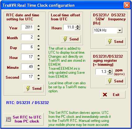
Hobcat - DS3232/DS3231 configuration
window
Note that these devices have two frequency output pins:
Epson RTC-8564
and NXP PCF8563 - I2C address
= 0x51
These two
devices are quite different, but share the same I2C address and interface.
The RTC-8564 has a built
in crystal and no trimming facility.
The datasheet implies that the frequency is set at the factory.
My sample has an error of 6 seconds per year.
The PCF8563 has an external crystal which needs a 20pF trimmer capacitor.
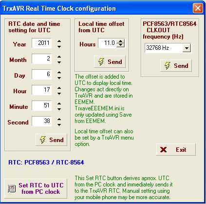
Hobcat RTC-8564 and PCF8563
configuration window
The CLKOUT options are: 32768, 1024, 32 and 1 Hz