80 character display
screenshots
Character displays
offer a good, low cost option for TrxAVR-Picastar
Any 40x2 or 20x4 NT3881D display panel can
be used, but we suggest the following:
- Optrex 40x2
white negative display (RS part no 620-4539 @ £22
+VAT)
- Optrex
20x4 white negative display (RS part
no 627-1769 @ £20 + VAT)
These displays are bright
with high contrast and a good size. (the 20x4 is 99
x 61mm)
This page shows images of my 40x2 Optrex
display (ie: Ian, G3VPX).
These images plus the brief comments plus the Picastar manual should provide
enough information to drive a transceiver
using these displays.
The layout is such that no item crosses
the centre line. This allows a simple switch to convert the display to 20x4.
The Right half becomes the top two lines and the left half becomes the bottom
two lines.
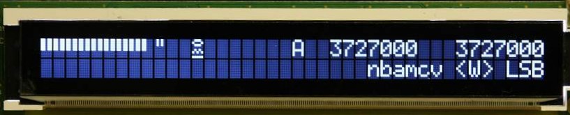
NT3881 displays have eight user definable
characters. Six of these are used in the S meter display below.
They are half and full S meter bars and 10, 20, 30and 40 dB over S9.
The remaining two are 25w and 130w power meter calibration labels.
(So you only have a scale calibration numerics for ranges of 25w and 130w !!)
- but this is fine for Forward and Reflected with a 100w PA .)
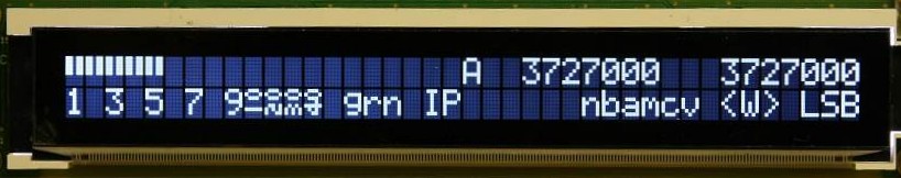
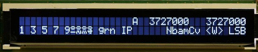
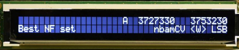
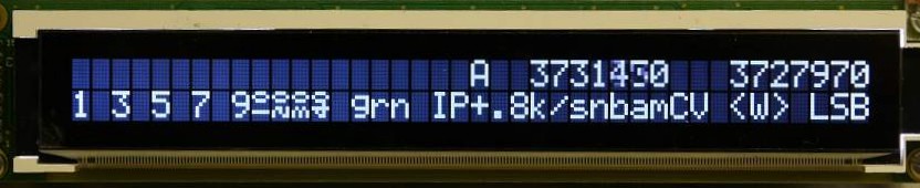
Initial 'home'
display on receive.
The left side is mainly S meter + DSP parameter set
colour + IP/NF (for best IP3 / best NF)
The right side is the two VFO frequencies, switch states
and mode (LSB, USB, CWL, CWU)
The filter switch indiation is <W> or >N<
on SSB and CTX andDEP on CW. (Context
and Depth... see Picastar manual)
VFO A is on the left and
VFO B on the right.
Within a 20 character width, there is space for two 8 digit frequency displays
+ VFO A/B labels + spaces.
However, there is no easy way of indicating which is the current VFO.
So we only label the current VFO. Hence in the display above: A is current.
Transmit display
showing forward power with 130w range.
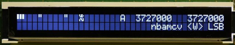
Transmit display showing reflected power
with a 25w range
Transmit display
showing SWR
They are soft key tasks
for Forward, Reflected, SWR
and Toggle Fwd/Ref/SWR
See TrxAVR keypads
DSP switches
showing Noise reduction and speech Compression on.
The letters nabamcv represent switches: Noise reduction, noise
Blanker, Auto-notch, Manual-notch, Vox/qsk and Compression
If they are upper case then the switch is on.
<W> indicates that the filter switch is in the Wide position.
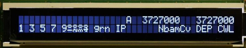
CW mode.
Filter switch = Depth, mode = CW LSB
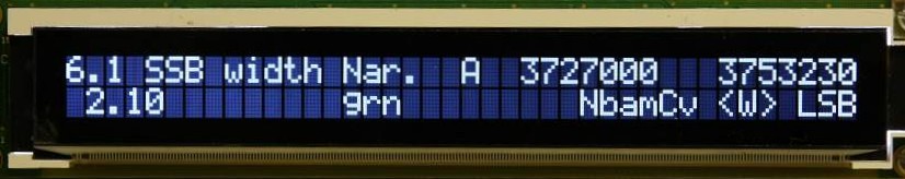
DSP parameter setting.
Parameter 6.1 is currently 2.10kHz
DSP parameter setting is accessed from the
'home' state either by:
- Key 8, as in Picastar.
The most recently adjusted parameter is displayed with its value.
Parameter navigation uses the keypad as in Picastar ( see Picastar
manual).
Rotating the Menu Encoder can also be used for parameter
navigation and will move
through all the available parameters ( the list excludes those parameters
fixed
in September 2008 by G3XJP which are prefixed with an 'x' in USER2b2.XJP)
The tuning encoder is used to change the value of the selected
parameter.
Key # or ESC to exit.
- Rotating the Menu Encoder
by 1 click will display the most recently adjusted parameter as
above. Keypad or menu encoder may be then used to navigate the parameter list..
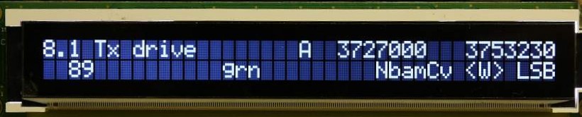
DSP parameter setting on transmit. Parameter
8.1 Tx Drive
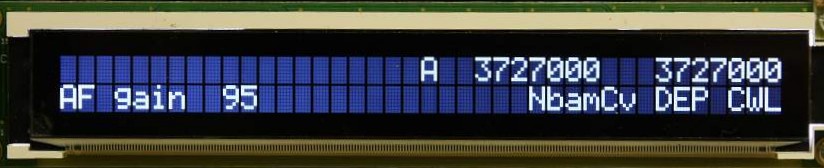
AF gain being
adjusted by turning Potentiometer B
Here, DSP parameter 2.1, AF gain has been assigned to one of the optional front
panel potentiometers.
The AF gain 95 display appears as soon as pot is moved and
persists two seconds after no further movement.
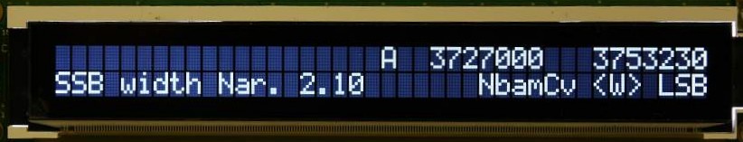
SSB width narrow
being adjusted by a rotary Encoder.
SSB
width narrow (parameter 6.1) has been assigned to an encoder.
The first click of the encoder displays
the message window showing current parameter value.
Subsequent clicks adjust the value. The value indication changes on each click.
The message window disappears 2 seconds after no further encoder activity, but
if another encoder
is turned, the message switches to it immediately.
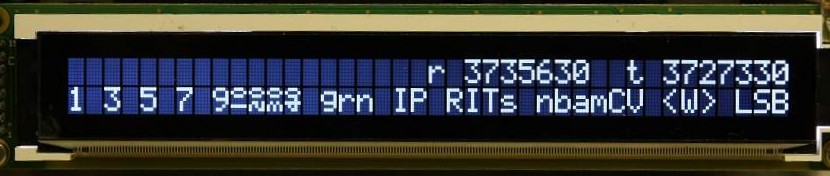
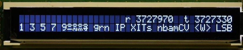
RIT mode - split
on - see Picastar manual. (The
s of RITs means split is on)
Refer
to the Picastar manual for use of the # key in controlling RIT/XIT.
Note that the VFOs are now labelled r and t
instead of A and B.
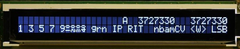
RIT mode- split
off. VFOs
revert to A/B labelling.
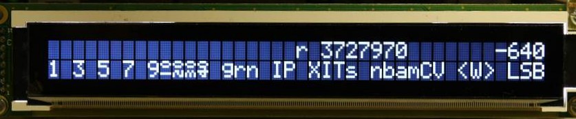
XIT mode - split
is on. Refer to the Picastar manual for use of
the # key in controlling RIT/XIT.
Note that the VFOs are now labelled r and t
instead of A and B.
XIT mode - split
is on, # key pressed to display transmit frequency difference.
# key behaviour is exactly as Picastar - except that if you hold
the # key, the transmit display changes immediately to frequency difference.
(In Picastar, this only
happens when you tune. Such a restriction is unnecessary here as we have two
VFO displays)
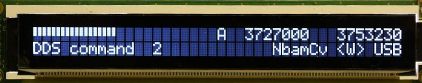
DDS commands - Long
key 2 press
This functions as in Picastar. TrxAVR is now waiting for the second digit to
complete the DDS command.
(see Picastar manual and DDS command list)
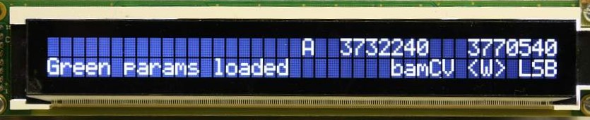
DDS command confirmation.
Some DDS commands give a confirmation message that persists less than 2 seconds.
Here, DDS51 has been keyed (or a soft key assigned to green params)
DDS command confirmation
- DDS48
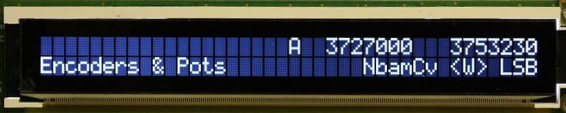
Menu key pressed
- first item is Encoders and Pots assignment.
Rotate Menu Encoder for rest of main configuration menu - or
press Menu again to select.
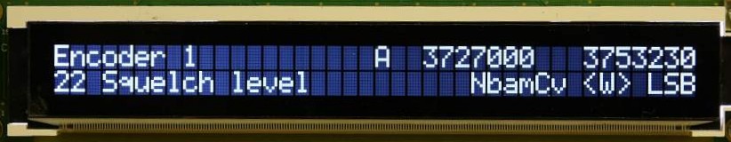
Menu key pressed
again - we are now in a list of 8 encoders and 2 pots
which can be accessed by rotating the Menu Encoder
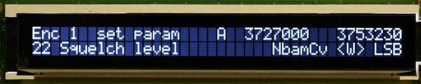
Menu key pressed
again - we are now able to select a DSP parameter to assign to Encoder 1.
The menu key rotates through the list of DSP parameters. We press Menu to select
and then ESC ESC to back out of the menu system.
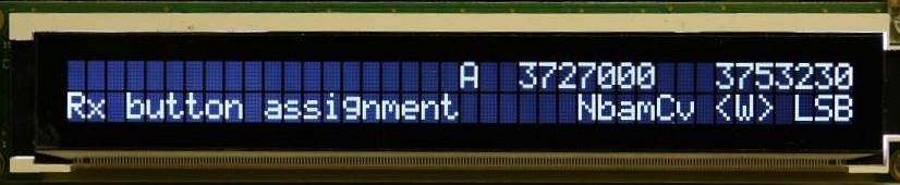
Main menu item:
Rx button assignment. This
menu item assigns one of 50 or so DDS, DSP and other tasks to soft keys A to
O.
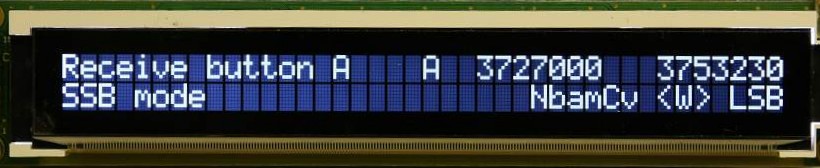
Menu pressed
- We are now in a list of 15 soft keys A to O which we can view by rotating
the Menu Emcoder.
SSB Mode (ie DDS11) has been previously assigned to soft key A.
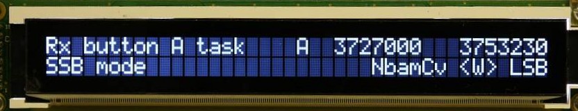
Menu pressed
again - we are now in the list of 50 available soft key tasks.
Rotate the Menu Encoder to select a task and then press Menu
to assign it to soft key A. Then ESC ESC to exit the menu system.
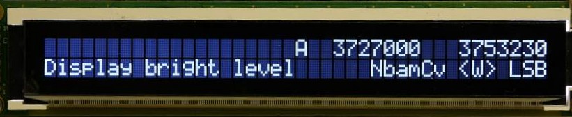
Main menu
item to control the display's bright level (ie the level when
it isn't dimmed!!) (We are in a list of Main menu items)
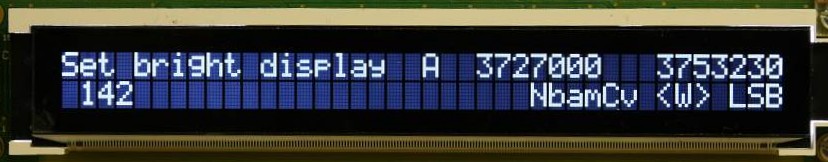
Menu key pressed.
Bright level setting. Rotate the Tuning Encoder
to set the level and then key Menu to confirm.
(The display brightness will change during setting)
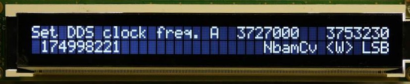
Setting DDS
clock frequency - Main Menu option.
You can also set this with DDS33 as in Picastar. See Picastar manual. DDDS33
uses signal generator mode.
This Main Menu facility does not use signal generator mode and so allows you
to fine tune the calibration by tuning the receiver to a
signal of accurately known frequency.
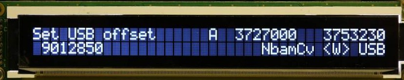
Main menu setting
of USB offset. This does
use signal generator mode and so is the same as DDS 31. (See Picastar manual)
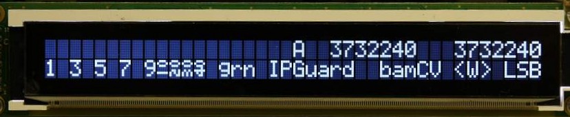
Guard channel monitoring.
DDS55 keyed. When
the other VFO is being checked (2 seconds in 20) it is labelled G.
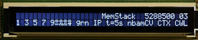
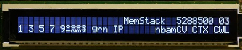
Memory stack scanning. DDS 56 keyed. Scan
interval shown: t=5s. 03 means Memstack 60 currently
on slot 3.
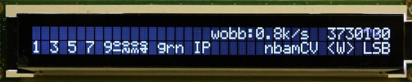
Wobbulator mode. DDS
58 keyed. From A to B. scan rate shown.
= 0.8kHz/sec.
Scan rate is set by the tuning encoder as in Picastar. The range of available
scan rates was chosen by observing a classic Picastar.
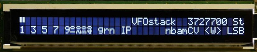
VFO stack tuning mode. DDS27 keyed. See
Picastar manual. St = a sticky slot (Vo
for volatile)
Memory stack tuning mode. DDS60 keyed. 03
- stack 0 (60) slot 3
Rate tuning mode. DDS22 keyed. Current
rate is 0.8kHz/sec.
TrxAVR-Picastar
home page