Homebrew-radios.net - TrxAVR -
minimum components for early testing
Some builders might wish to assemble their TrxAVR
board in a way that allows testing of USB connectivity
and ATmega2560 programming at an early stage in the programming.
The advantages of doing this are:
- It gives confidence that the system
works before installing the remaining components.
- If there is a hardware fault (eg: non-soldered
ATmega2560 or FT245R pin) then it is easy
to trace because there are few components to check.
My rig uses a home-made TrxAVR-A controller.
I needed to assemble one of Glenn's TrxAVR-B boards to test a prototype Colour
TFT board.
(designed by Chris Stake, drawn up and manuactured by Glenn and programmed by
Gerard)
The connection to the colour TFT display I2C is 3 wires: data, clock and ground.
There is a 4 pin
I2C bus connector adjacent to the 24LC512 EEPROM for this and other I2C devices.
So I didn't need the parallel display connecting components.
Even without a display connnected, the minimum configuration
described below allows you to:
- Test USB connectivity
- Use Mprog to configure the FT245R USB
chip.
- Observe that Hobcat reports: USB:
TrxAVR control baord (FT245R) s/n A9RUL680 etc
- Connect the AVR programmer (AVRISP2
or Ponyprog)
- Set the fuses and program the Atmega2560.
- Observe the message: TrxAVR v 1.38
ready (no DSP load delay delay until DSP code loaded)
- Run Hobcat's Hardware setup screen and
configure (Do not specfiy a colour TFT dispaly unless
you have one connected - the repeated I2C waits will slow the processor)
- Observe meaningful data in Hobcat's
debug screen. (The variable names all come from TrxAVR)
- Load DSP code and parameters (C:\TrxAVR
folder needed - set up same as C:\Star + trxavreemem.ini)
- Reboot and obvserve 20second DSP load
delay (can't see it as you have no display)
(No DSP unit needed)
- Run Hobcat's DSP window and see meaningful
parameter values received via USB from TrxAVR.
- Use Hobcat to upload stacks, slots and
other data from trxavreemem.ini.
- Use Hobcat to upload default SWR forward
and reflected claibration data - observe correct checksums.
- Use Hobcat to upload AD603 calibration
curve (used by DSP monitor)
- Run Hobcat's DDS window and see meaningful
VFO A and B frequencies. Band and mode changing
should work.
All the above testing can be done with
no display and no keypad.
The minumum components to achieve this
are:
Connectors:
- power
- 6 pin programming connector
- USB connector
Other components:
- one Atmega2560 = IC1
- the USB chip - FT245R = IC5
- a 5v regulators (IC2)
- The 24LC512 EEPROM - IC4 - in a socket
- Two electrolytics C33, C11 and C14
- 100nF decoupling C1, C10, C6, C26,C27,
C7
- The reset capacitor C19
- The Xtal capacitors (18pF) C15 and
C16 .. and the Xtal !
- Resistors:
- USB - R58, R59 (and R83)
- I2C pullup R8 and R9
- FT245R Txd and Rxd pullups R28 and R29
- Reset pullup R7
- And the two missing earth links - see
Glenns web site.
And that's all ...... and the board looks
rather empty !
Double click
the following images for the high-res version.

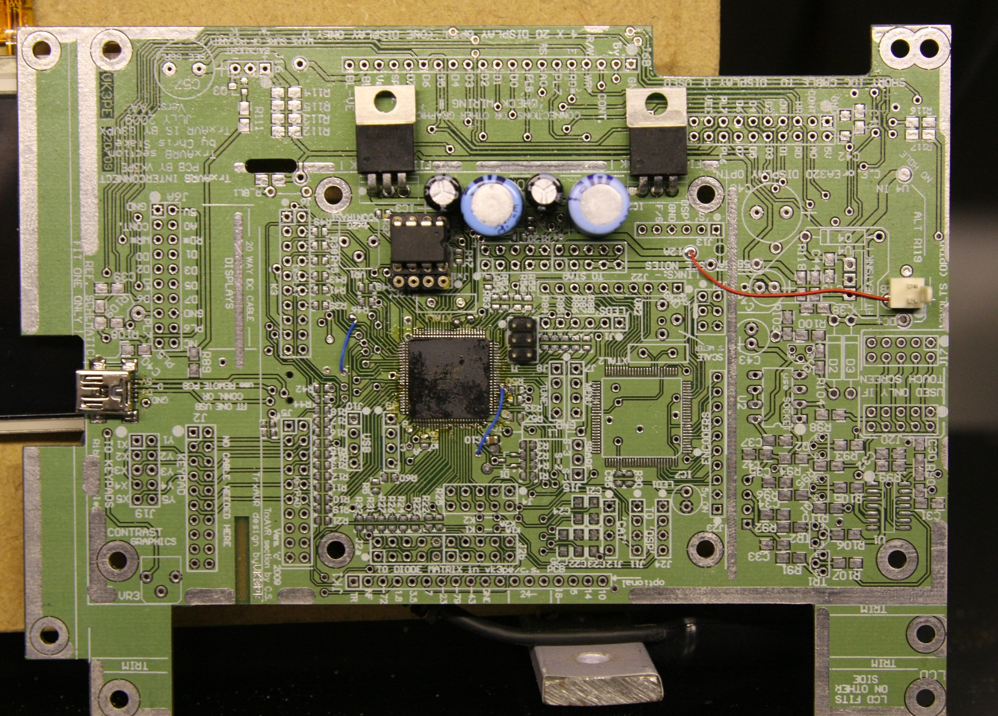
TrxAVR-B - minimum config topside. Note that both 5v regulators
+ caps are installed here (only IC2 needed)
I2C connector installed adjacent to 24LC512 EEPROM.

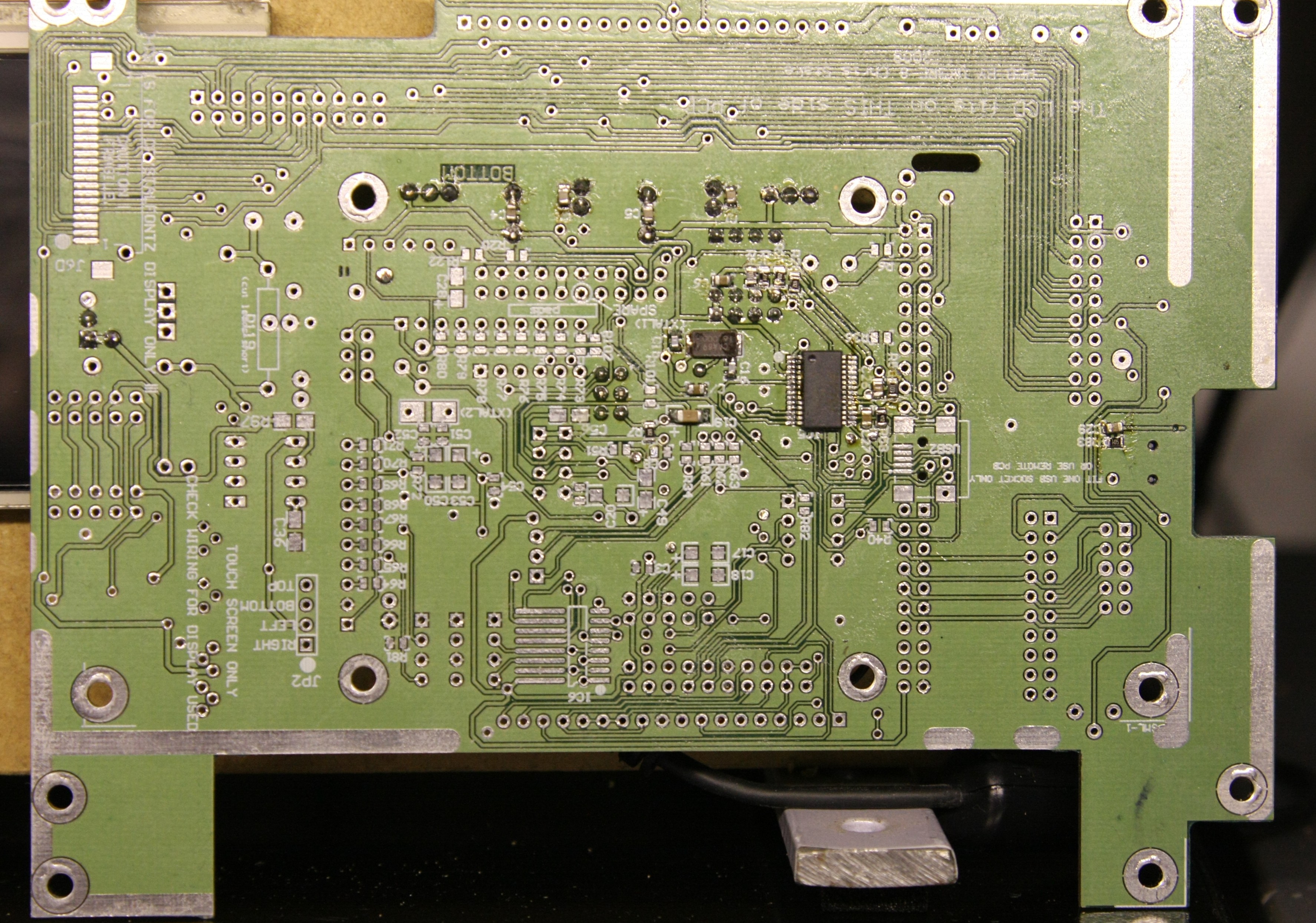
TrxAVR-B mimimum configuration -
bottom side. - note: SMD
Xtal used here
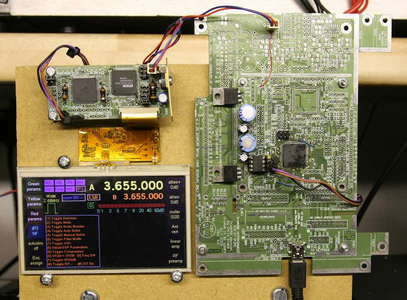
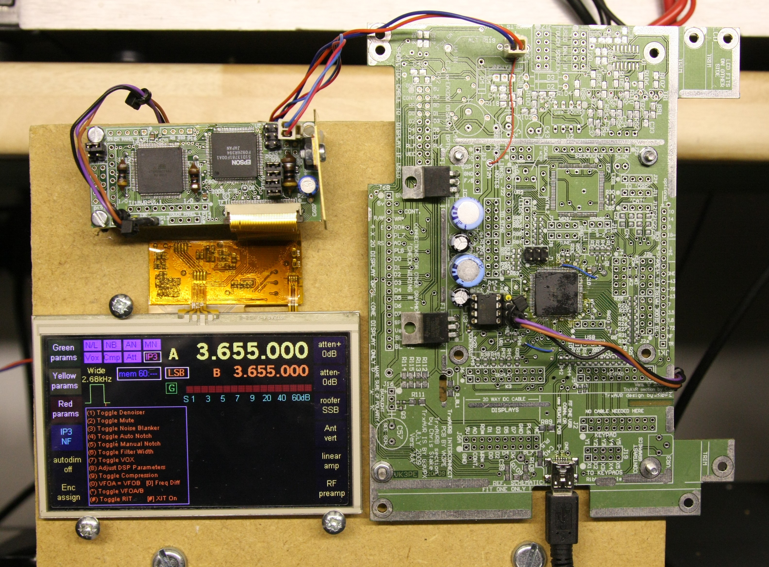
Minimum configuration driving TftAVR and a Truly 480x272 4.5inch display
TrxAVR-Picastar
home page