G3VPX TrxAVR-Picastar in a box
I finally demolished my development breadboard
rig and built it into a box. (Mid July 2009)
The rig was completed wih colour TFT, PA3AKE front end andPCA9555 board Jan
2010.
The box is all double sided PCB construction.
The design drawing pdf can be downloaded. (The position of timer, diode logic and TrxAVR-A boards was subsequently changed)
A fan is installed under the two PA heatsinks. It has on/off control from thermistors in the heatsinks.
The rig now has a colour TFT display and
a PA3AKE BPF and roofer/mixer unit.
(The earlier photos with a mono graphics display are at the end of this page)
Click the images for the high resolution versions.
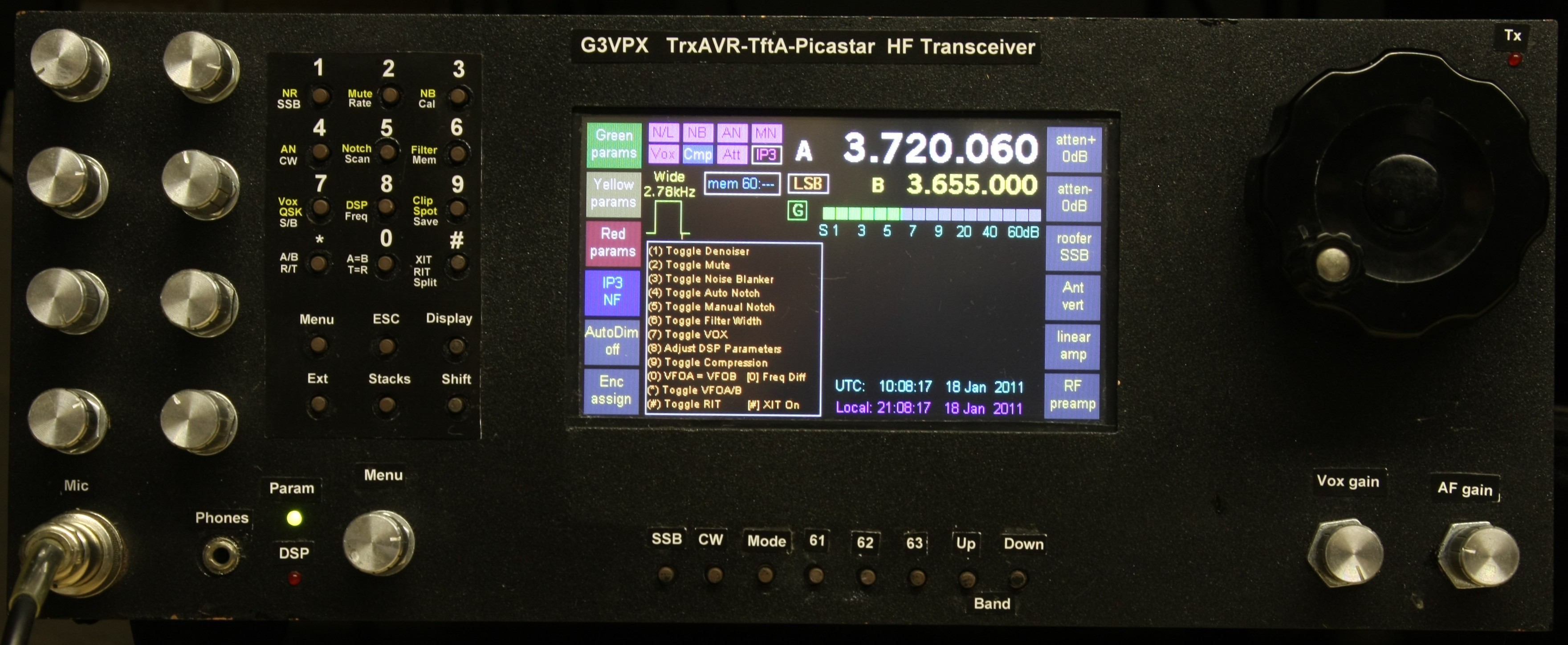
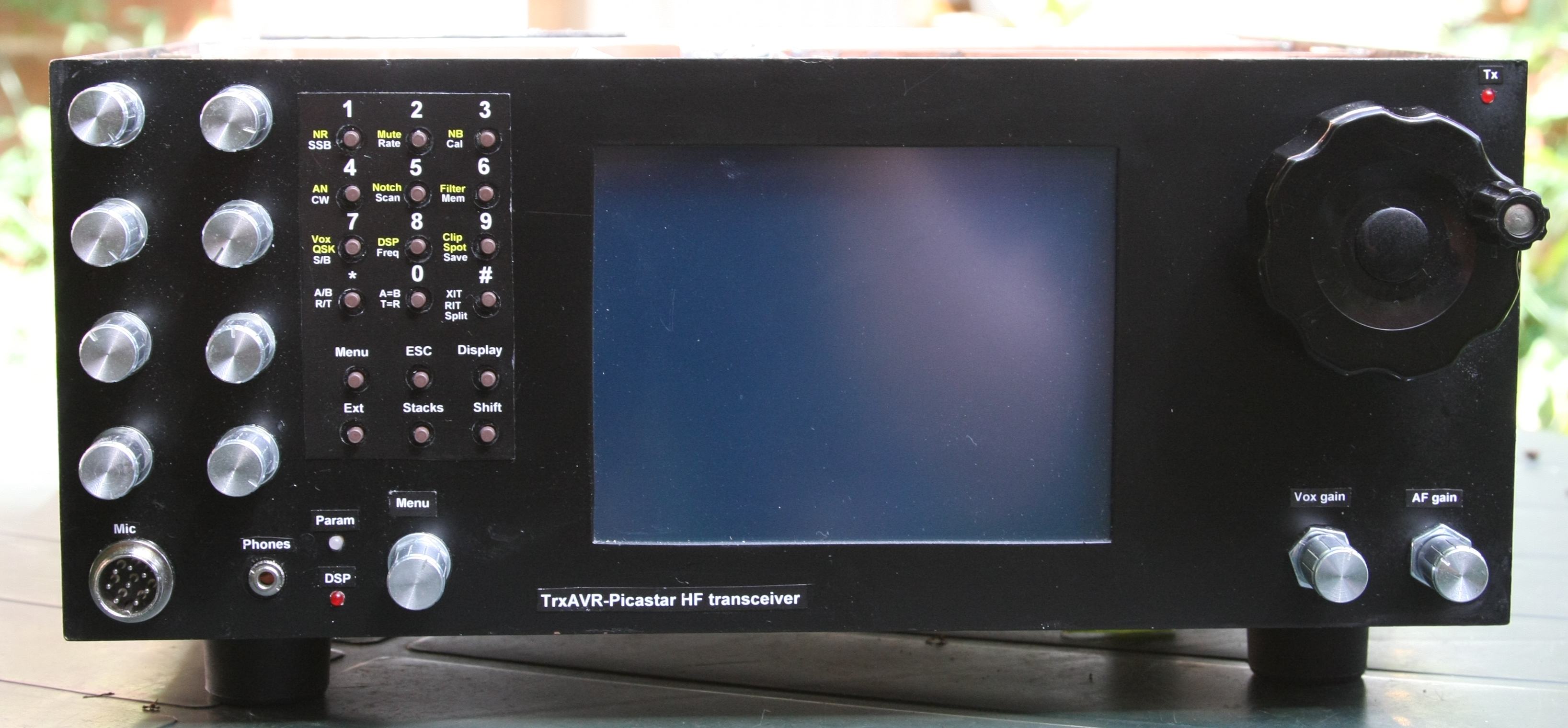
Current front panel with Colour
TFT display.
When I purchased the colour TFT display I somehow, unintentionally bought a
black aluminium bezel for it.
This was ideal for changing from the larger 320x240 mono display to a colour
display: It mounts the colour TFT panel, and just
covers the larger hole that was previously
needed by the mono graphics display. In real life it looks black ... not grey
as in the photo!!
The extra space created in the front
compartment accomodates the PA3AKE mixer/roofer unit and gives much better access
to
the TrxAVR-A board.
I also fitted eight extra switches below the display.
Labels are color laser printed on HP glossy brochure paper
and glued with a paper-glue stick for
easy removal.
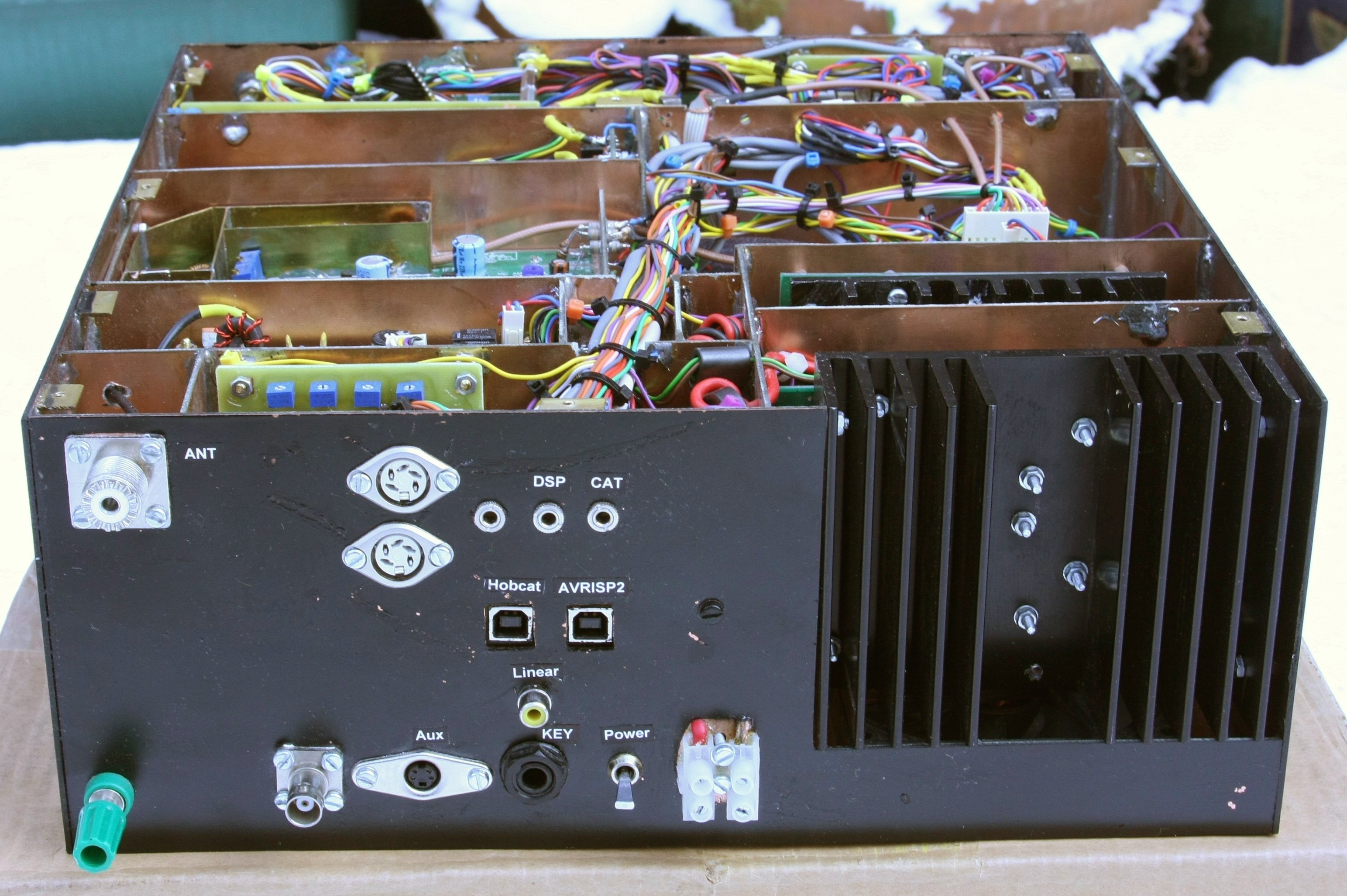
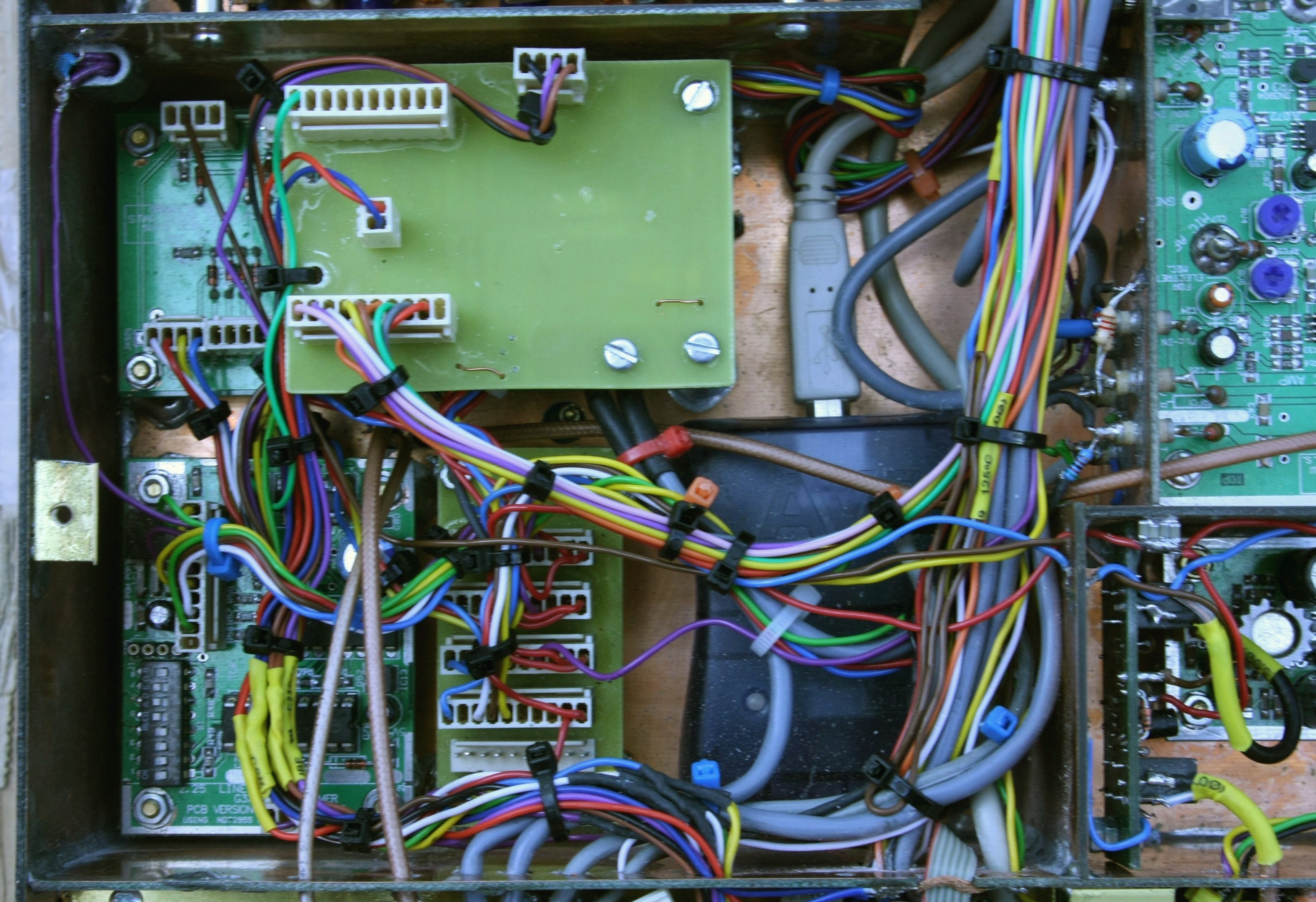
Rear view. A small PCB
carries two USB-B conenctors. I have installed an AVRISP2 programmer in the
rig.
This will stop the processor if not connected to the PC - so a diode applies
+5v to the USB 5v line to keep the programmer energised.
The two 5-way DIN sockets provide 8 open collector outputs from a PCA9555, I2C
to 16 line chip (=+ darlington drivers)
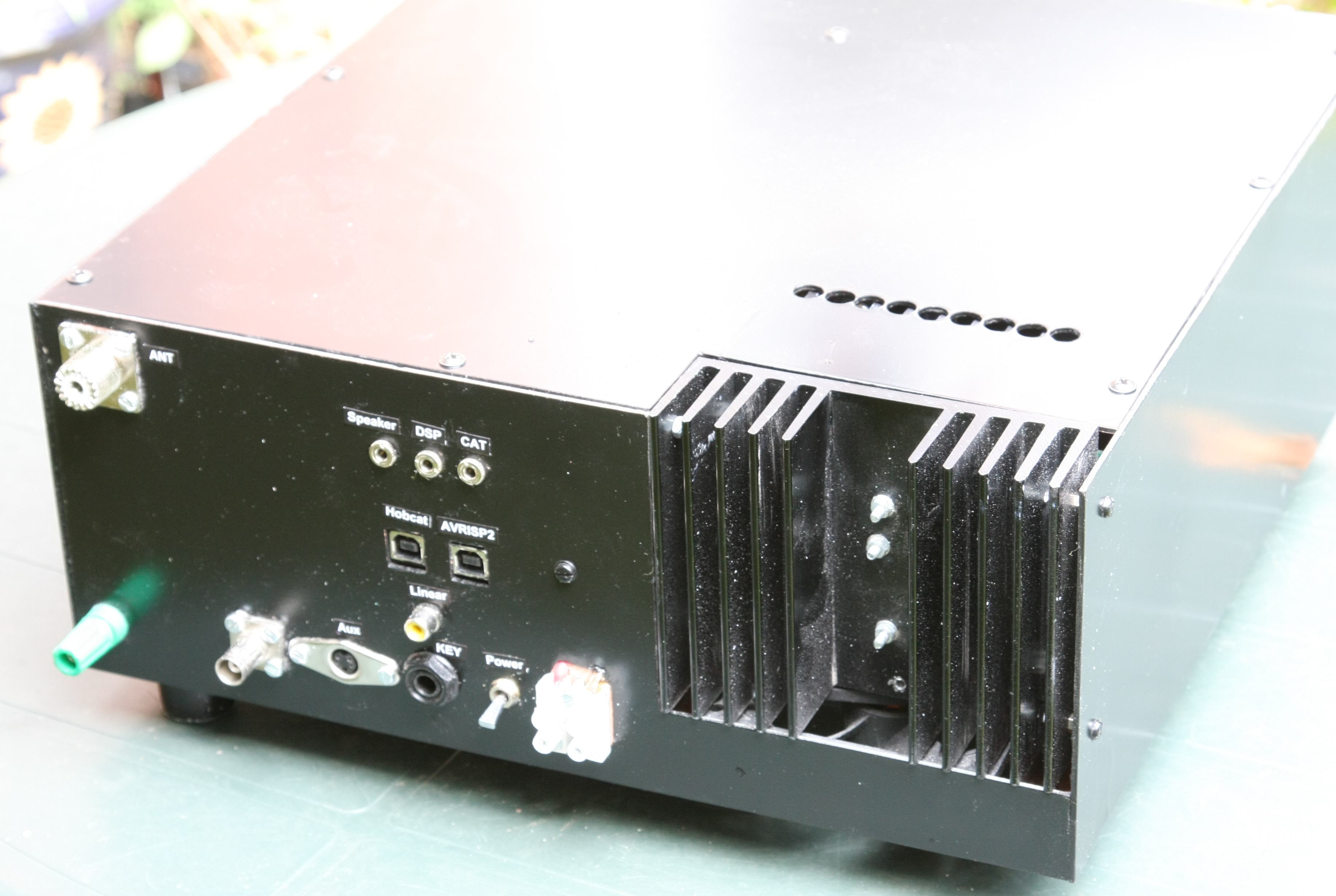
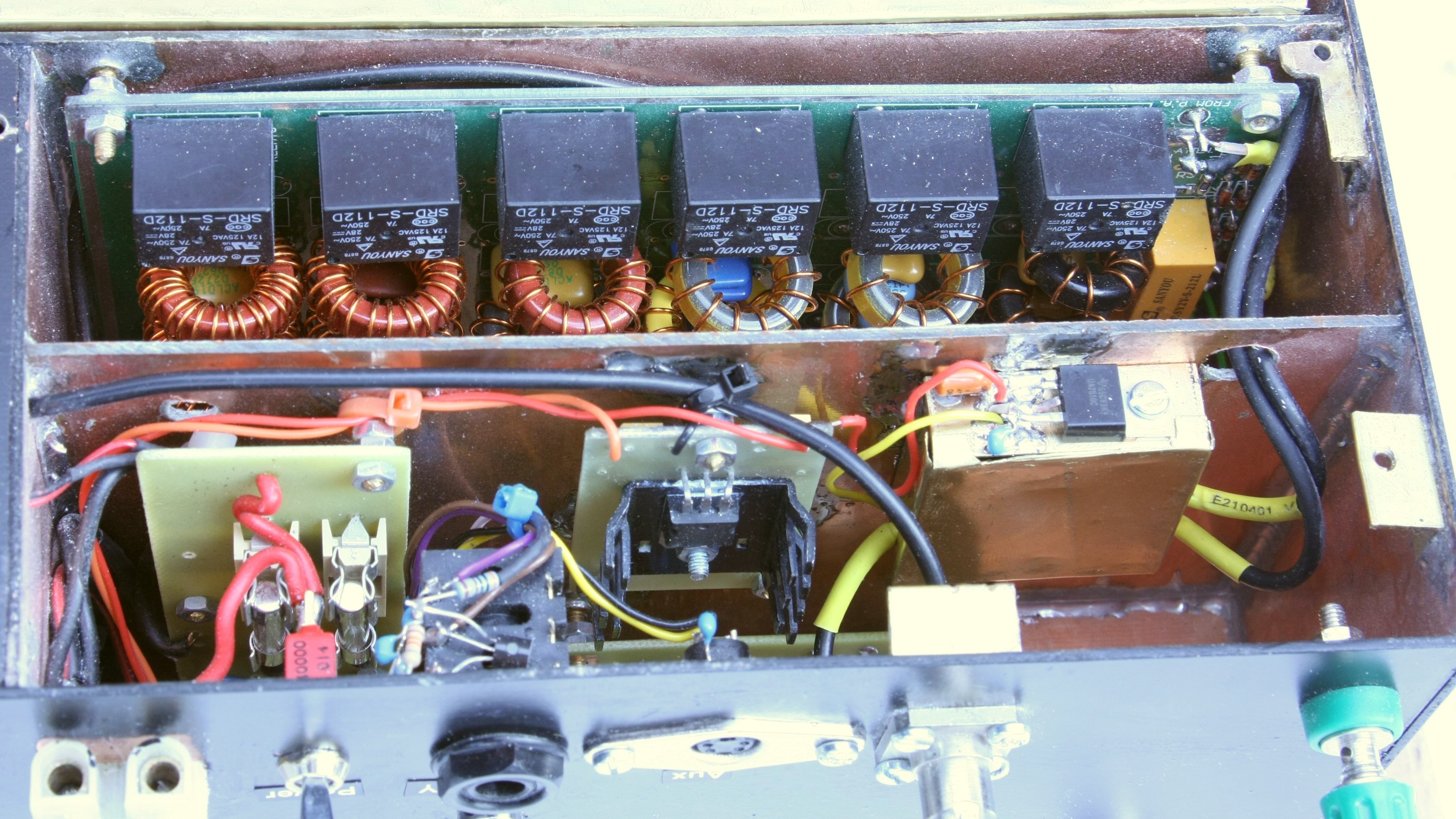
Rear oview showing ventilation holes for 20w Mosfet PA heatsink.
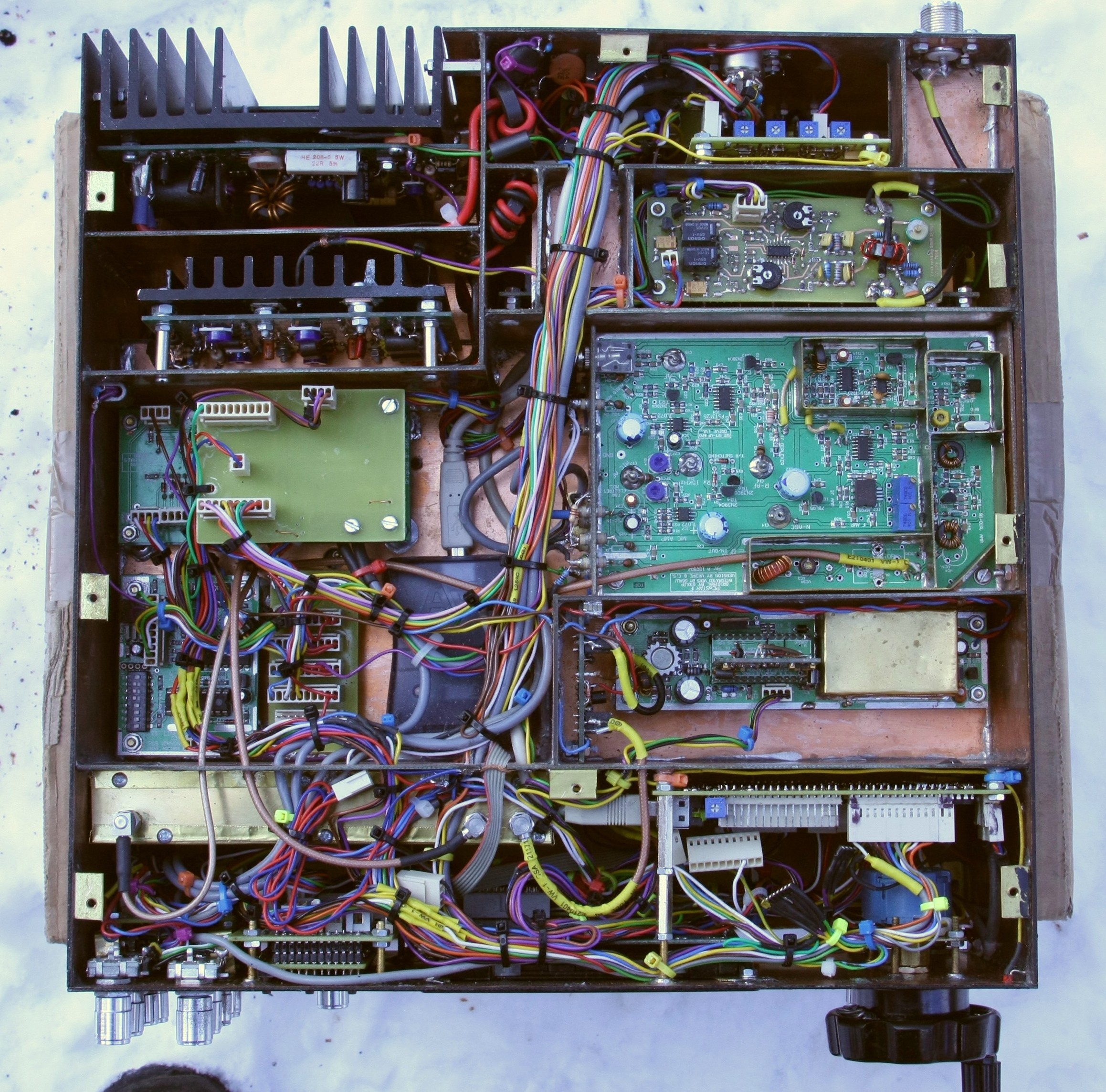
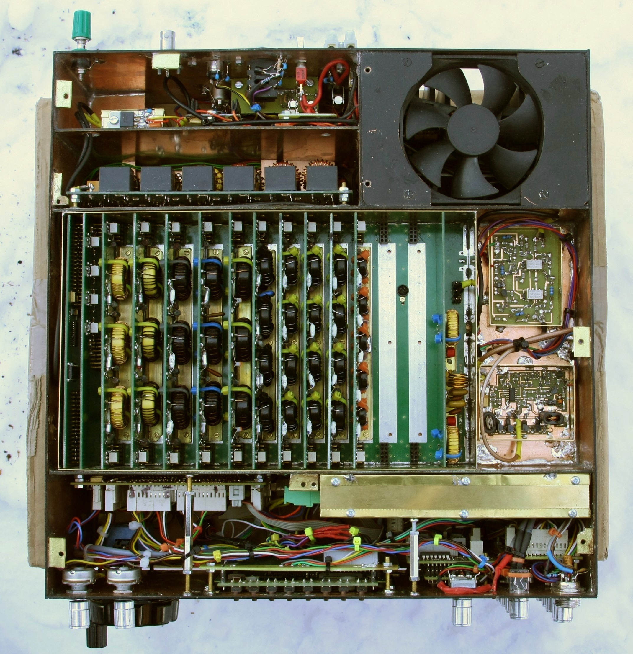
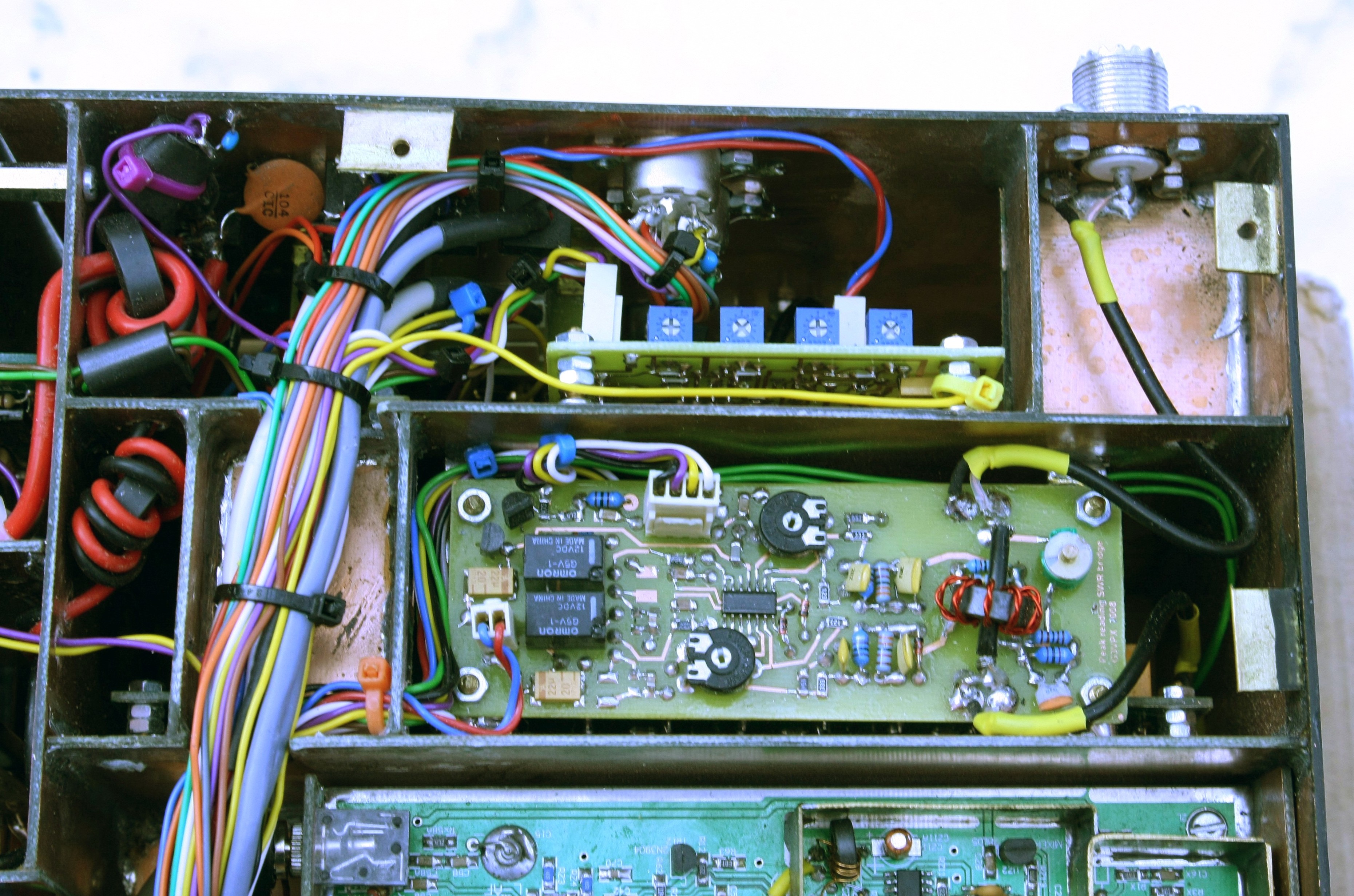
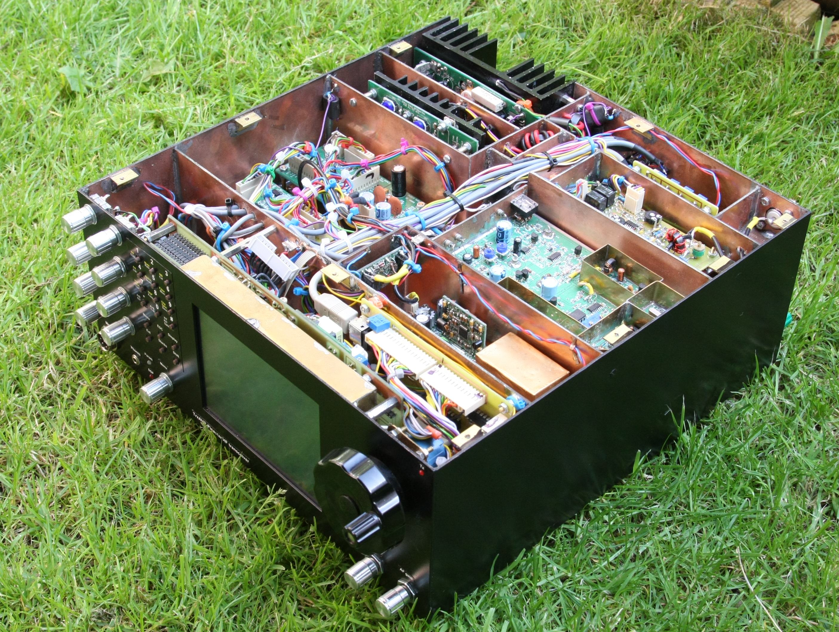
Top view.
The board with four trim-pots in the rear connector compartment is a thermistor
fan controller.
In front of it is a PeakSWR board under the LPF unit.
The PA3AKE roofer/H-mode mixer unit is in a brass box in the front compartment
(with 3 SMA connectors)
Note the AVRISP2 programmer in the centre (grey platic box).
The 'bare' board mid-left is the PCA9555 IC2 to 16 line unit (chips underneath)
The PA units are located so that the cooling fan cools them both.
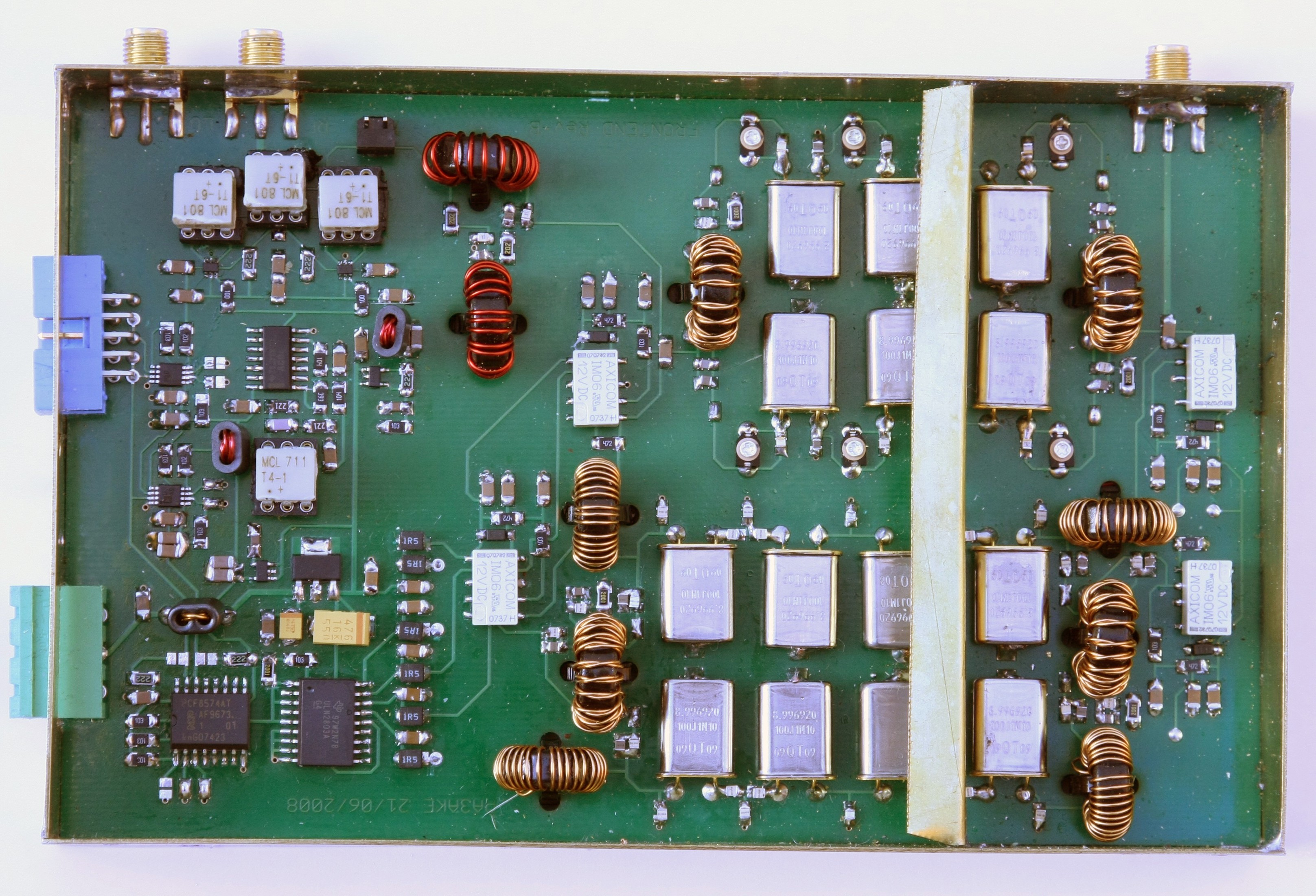
Bottom
view - with rf screening removed. In the centre is the PA3AKE
BPF (I2C controller leftmost, IF notch filter rightmost)
This uses polysterene capcitors. (The plate ceramics shown on the 20m unit have
now been replaced !!)
The flter boards provided for the alternative use of ATC ceramic caps (about
1 ukp each!)
Unfortunately, the space in my box wasn't quite big enough. Somewhat unwillingly,
I had to trim 2mm
off each side of the motherboard and plug-in boards and 2.5mm off the top off
each plug-in board.
There is clearance to do this and the result was quite neat.
Bottom right: PA3AKE roofer/mixer in its brass box.
Mid right: MAX2611 rf preamp and 4xJ310 amp (FST3126 switched). The 4xJ310 amp
is identical to that on the Picastar magic roundabout.
Top left is a BPF switching unit to switch the BPF between antenna input on
Rx ( from LPF unit) and PA input on Tx.
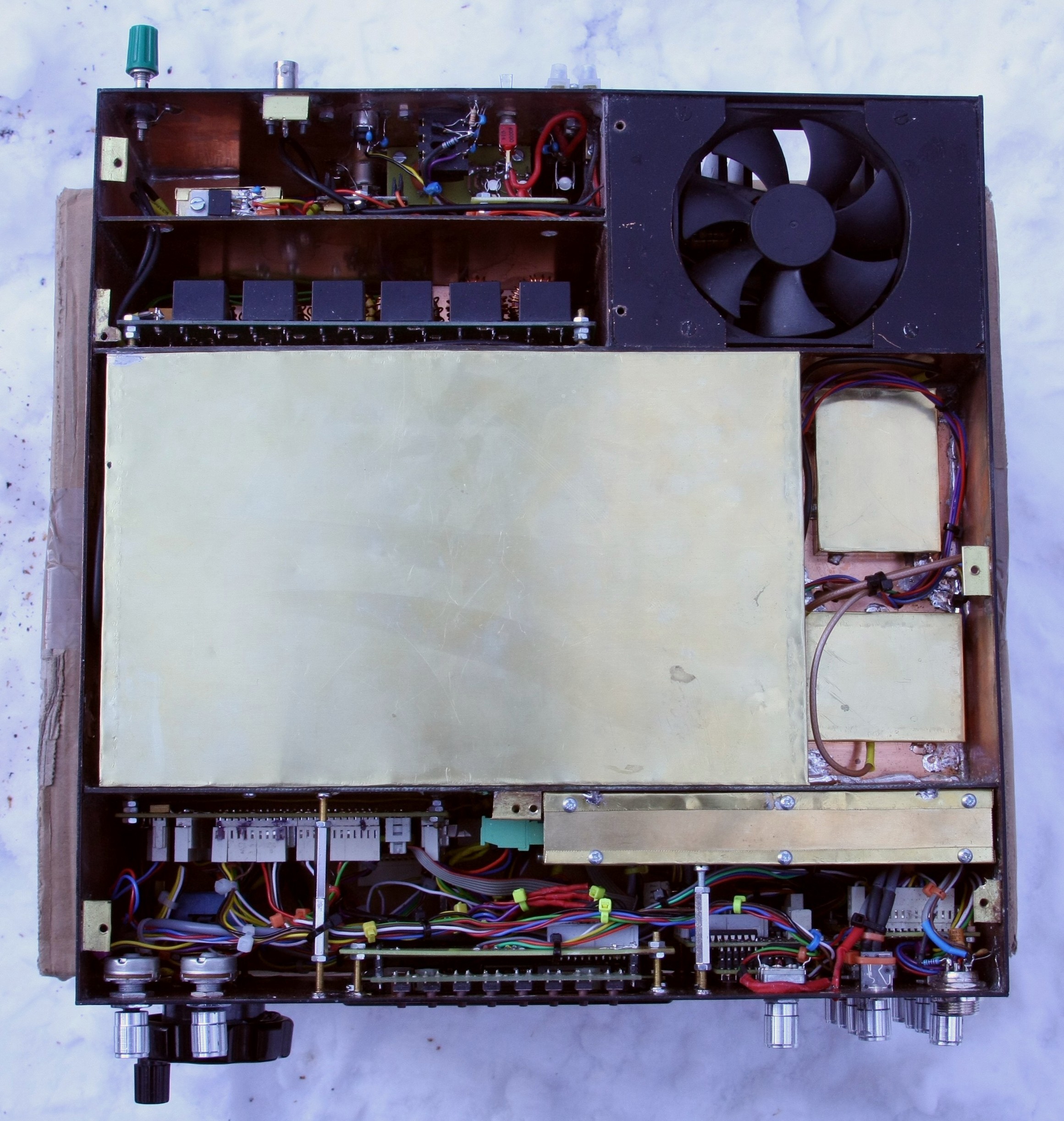
Bottom view with RF screening in
place.
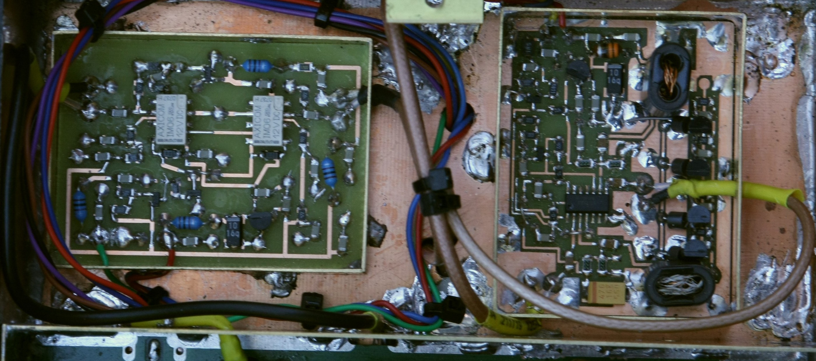
Left: MAX2611
RF preamp switched with Axicom IMO6 relays as used in the PA3AKE
units (Has 6dB input pad - overall gain is 12dB)
Right: 4xJ310 amp - bidirectional
switching by a FST3126. (Measured gain = 16dB)
This amp is between roofer and IF unit (Any gain before the roofer would compromise
PA3AKE's huge effort to minimse IMD.)

Preamp and 4xJ310
amps with screening lids fitted.

PA close
up top view. Note the thermistors in holes drilled in the heatsinks.
PCA9555 I2c
- 16 output unit. (Chips on underside of board)
8 outputs to two external 5-way DIN sockets.
One internal for premap switching. (Hobcat's I2C configuration allows for transmit-only
activation)
Note the built in AVRISP2 programmer.
PeakSWR unit
in LPF compartment
Thermistor fan controller (4 trim
pots) This monitors the heat sinks of both PAs.
View showing BPF switch in screening box on right.
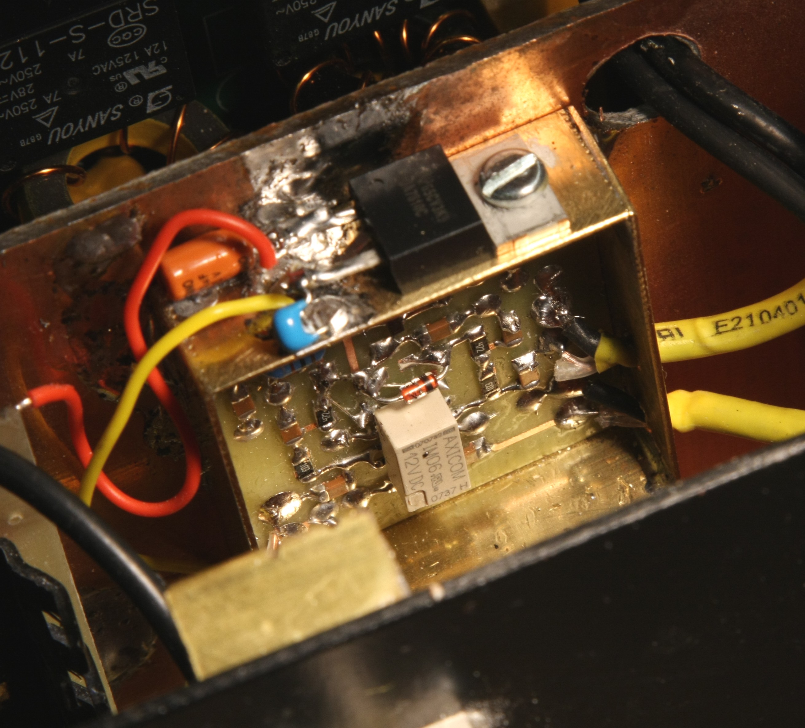
BPF
switch. Switches
BPF to antenna input from LPF unit on Rx, and to PA inout on Tx.
Uses Axicom IM06 relays as used in the PA3AKE units.
H-mode mixer
and roofing filter unit - topside
The CW filter (top
right) requires careful adjustment of the six trimmer capacitors.
The SSB filter (bottom right) required no adjustment.
The H-mode mixer is top left. The tiny FSA3157 switches are located just below
the Minicicuits transformers.
At the left are two AD5321 I2C-DAC chips which provide for mixer bias and squarer
symmetry adjustment
which is performed from Hobcat via USB.
The mid-filter screen protrudes above the edges of the box so as to spring against
the lid for good electrical contact.
Martian, PA3AKE evaluated 7 switch types and 12 transformer types in order to
achieve optimum mixer performance.

H-mode mixer
and roofing filter unit - underside
LO imput is the left most SMA connector.
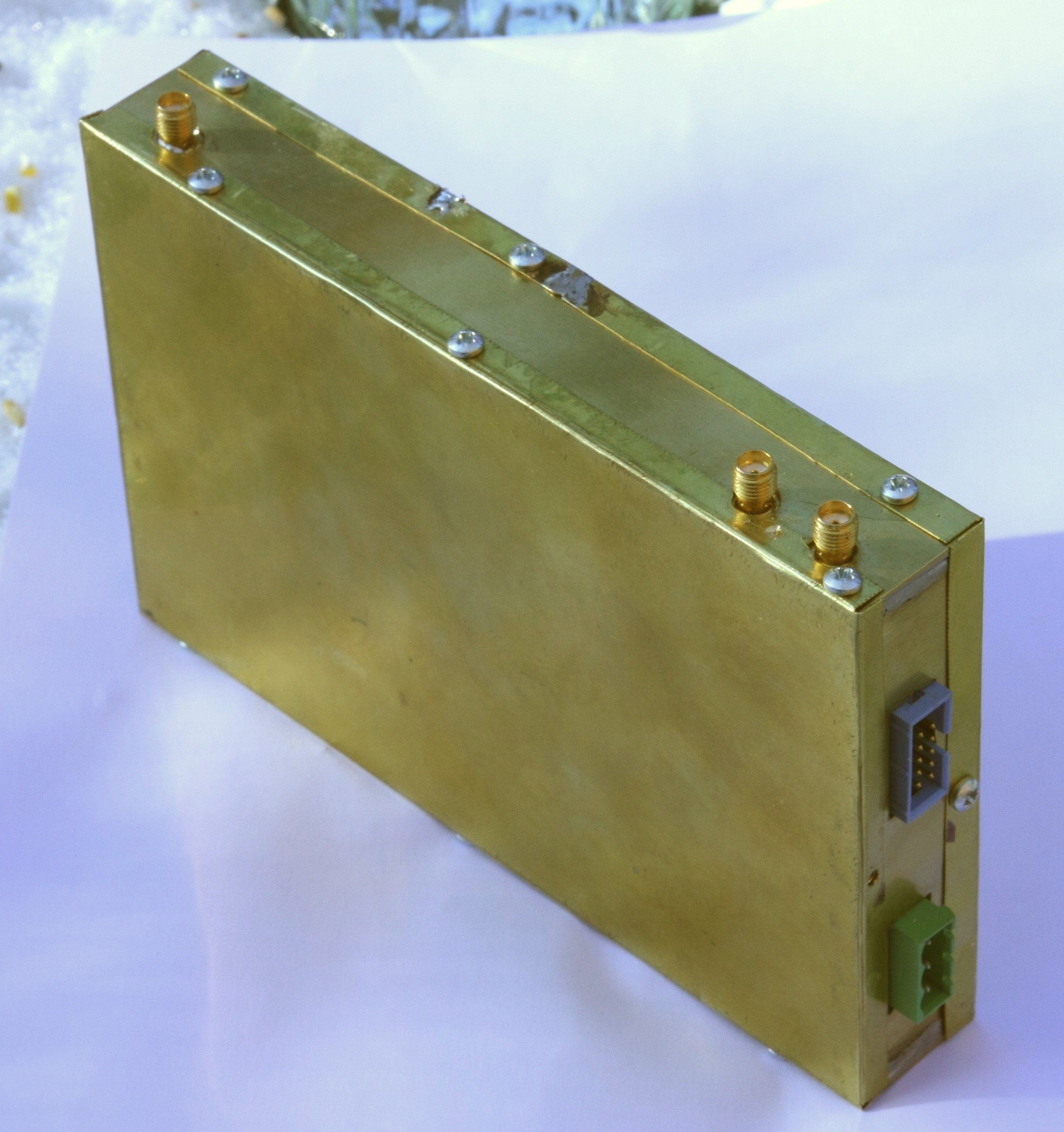
H-mode mixer
and roofing filter unit - box. Sides
0.7mm brass. Lids 0.3mm brass.
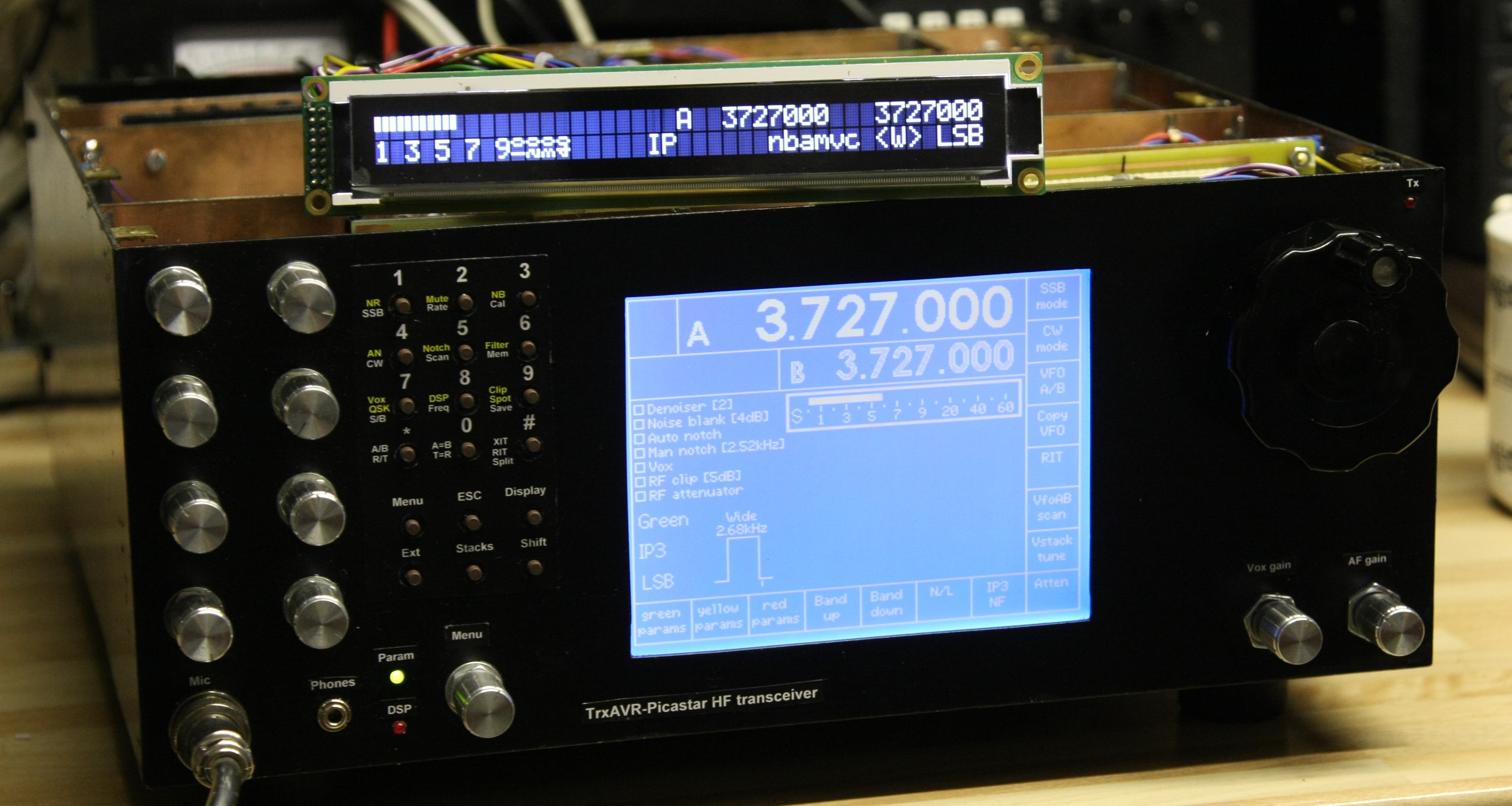
Earlier photos when the rig had a 320x240 mono graphics display.
Original Font panel - with mono
graphics . Labels are color laser printed on HP glossy brochure paper
and glued with a
paper-glue stick for easy removal.
The display has a touch panel and so the vertical row of eight buttons is omitted.
This saves panel space. (the E320 motherboard
is still the same size, but it is 3cm behind the panels and so the button space
could be used)
Top
oblique view showing case construction.
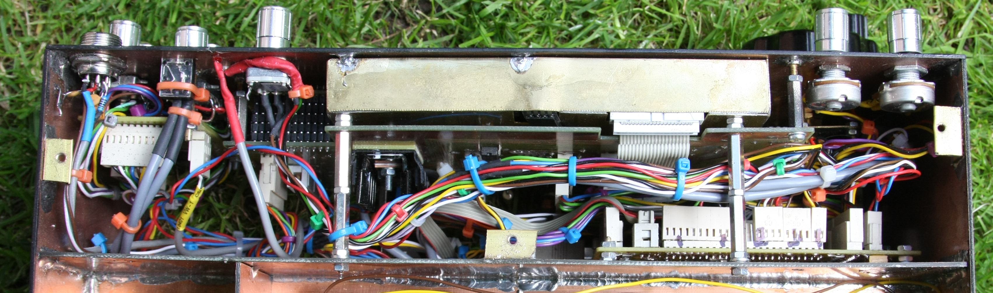
Display
compartment underside. TrxAVR-A is on the right. Note
the programming ribbon cable left in situ.
Support for the box's top and botton are soldered brass angle. Self tapping
flat headed screw are used (car spares shop)
On the left is the Encoders8 board mounted behind the encoders.
Character display plugged in, and dual display selected in Hobcat hardware setup.