
TrxAVR-Picastar software specification
Memory usage
In TrxAVR-Picastrar version 1.67 described here, the ATmega2560 memory usage is:
Hobcat
TrxAVR-Picstar communicates via USB with the PC-based Hobcat companion program.
Hobcat
is installed by HobcatSetup.exe.
The latest HobcatSetup.exe is run to update an existing installation.
HobcatSetup.exe
Hobcat
Hobcat is written in Delphi 6 with addons: Developer Express Grids and Raize components.
Its features are:
TrxAVR_PicaStar
The Picastar transceiver is controlled
by a 4x3 key pad and a tuning encoder.
TrxAVR-Picastar can also be controlled in the same way.
The Picastar keypad operation is summarised as follows:
TrxAVR-Picastar
has all the above keypad functionality exactly as Picastar.
The only difference is that it displays extra information related to the control
actions,
and there are additional alternative control facilities.
The amount of information
displayed depends on the type of display used.
That detail will be not be discussed here.
It
is shown/discussed in the pages devoted to each display type.
4x3 keypad control is
documented in the Picastar User manual and so will not be repeated here.
We have made the TrxAVR-Picastar 4x3 keypad behave
exactly the same as Picastar so that:
Therefore:
The term 'home' will be used to describe the startup state where the keypad is fully active.
Summary of extra features added by TrxAVR-Picastar:
VFO
displays
Both VFO A
and VFO B frequencies are displayed to 1Hz (although the minimum
tuning step is 10Hz)
The VF0s are labeled A and B. In split mode,
the labeling changes to R and T
In graphics displays, the inactive VFO frequency is grayed to make it less prominent.
In guard channel monitoring, the guard channel is labeled G.
DDS commands
A long press of the 2 key displays; DDS
command 2_ The second numeric is then keyed.
Some commands then display a transient message explaining what has been done.
eg: RF atten on
Such a message is not needed for commands such as DDS27
= VFO stack tuning, as the subsequent
display makes it obvious that VFO Stack tuning is selected.
DDS 82,
84 85 and 86 provide
SWR meter control (Toggle, Forward,
Reflected and SWR)
This is only applied to the character display. The 320x240 graphics shows all
three simultaneously.
(These switches are also available as soft key functions.)
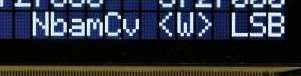
DSP switches
In character displays and
the 128x64 mono graphics display, these are displayed as single
letters,
lower case = off and upper case =on.
SSB filter width is shown as <W> or >N<. CW
filter mode is shown as =C= or _D_. (context
or depth)
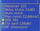
In the EA320 graphics display,
switches are displayed as check boxes and some show associated
parameter values, eg: denoiser level.
In colour TFT switch indicators change colour (poor photo)
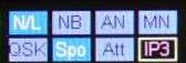
The
Menu Encoder
This is a low resolution encoder used for stepping through menu, parameter and
F+M slot lists.
(F+M slot lists viewing is only available with 320x240 graphics)
Most of these lists are circular.
In 320x240 graphics they are presented as a scrolling list with a central highlighted
item position.
DSP
parameter setting
This is entered from home
by keying 8 or by turning the menu encoder
- either action displays the
the most recently adjusted parameter (or 8.1 after startup)
Rotation of the menu encoder moves in a circular loop through all the available
parameters.
At any time the keypad can take over parameter selection as in the Picastar
manual.
Parameter values are adjusted by rotating the tuning
encoder.
The parameter list is appropriate to mode (ie CW or SSB) and excludes parameters
that were fixed
in September 2008 by G3XJP. (ie those preceded by an 'x' in User2b2.xjp)
Exit from parameter setting back to home is by: ESC
or # keys OR turning a parameter assigned
encoder
or pot OR after an optional timeout of 1 -
60 seconds (0 = no timeout) (Saved in trxavreemem.ini)
Parameter adjustment is immediately applied
to any extra displays of the parameter's value,
eg: the graphic filter shape display and values associated with
switches.
Filter Display
A graphical representation of DSP filter shape is shown. It changes as the controlling
parameters
are altered. Typical images are show below. The depth graphic changes to show
depth (0-90dB)


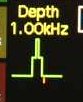 This
TFT images shows the carrier point (now actually on all filter graphics)
This
TFT images shows the carrier point (now actually on all filter graphics)
Alternative
tuning modes
Operation
by key pad and tuning encoder is exactly as in classic Picastar.
eg:
key DDS 56 to scan current memory stack and
then use the tuning encoder to control rate.
Example text displays for graphics and character displays are shown in red
bold.
Memory
stack tuning
has an indication of stack and slot number.
Graphics: 60
61 (stack 0 slot 1 - but 60 and 61 are codes entered to access
these slots)
Character: 01
... because there is less space.
VFO stack tuning
Graphics: VFO Stack mode
Volatile slot no 1 etc
Character: VFO Stack
, the frequency and
Vo for volatile or St
for sticky.
Memory
stack scanning
Graphics: scan memory stack,
mem 60 64 (changing) scan
delay = 2s
Character: MemStack
frequency 03
stack 0, slot 3(changing) t=2s
VFO
A and B scanning
Graphics: Scan VFOs A
and B Scan delay = 4s
Character: t = 1s
and labels A
and B alternating with the scanning
Wobbulator
mode
Graphics: Wobbulator
mode 0.8kHz/s
Character: wobb:0.8k/s
Guard channel monitoring
Graphics: Guard channel check every 20 seconds.
VFOs are labeledA and G.
The
G channel changes from gray to white when checked
Character: Guard The
labeling flips from A to G
when checked
XIT
and RIT
The # key works as in Picastar.
RIT and XIT displays:
Graphics: RIT [split on]
RIT[split off] XIT[split on]
XIT[split off]
Character: RITs RIT XITs
XIT
With split on, the VFOs are labeledR
and T. With split
off, they are labeledA and B.
Stacks
and slots
Please refer to the Picastar manual for description of Memory, VFO and Band
stacks and slots.
TrxAVR-Picastar uses the same DDS commands and the Stacks operate in the same
way.
TrxAVR-Picastar increases the visibility of the 61 sticky slots and 23 volatile slots:
Stacks key
/ menu (320x240 graphics only at present)
The Stacks key displays a three item menu
to select Memory, VFO or Band
stacks.
The menu encoder the highlights a stack type and then the Stacks
key selects it.
Slot data formats are:
The Stacks key will load the highlighted slot (not for VFO slots)
Stacks
soft key and touch pad tasks:
There
are fourteen soft key / touch pad tasks available for Memory Stack control:
User assigned encoder and potentiometer controls.
Two
front panel potentiometers can be assigned to DSP parameter control.
If the Encoders8 unit is installed, then eight front panel
low resolution rotary encoders can be
assigned
to DSP parameter control. (Encoders8 is built into TrxAVR-B)
The assignments are made on the transceiver using a configuration menu option.
The assignments are stored in the Atmega2560's internal EEPROM. All the internal
EEPROM data
can be transferred to and from the trxavreemem.ini file.
When a control is turned,
a transient popup window appears to identify the control and
display the value.
If the control is operating on filter width, depth or carrier offset (= sidetone
pitch in CW mode)
then the filter graphic changes during the adjustment.
User assigned soft
keys
TrxAVR-Picastar
allows you to assign tasks to:
The above mentioned bottom
and touch pad assignments are made separately for receive and transmit
and the labeling changes on R/T switching.
The tasks are selected from a list of 65 DSP, DDS and other functions.
The 320x240 graphics displays
provide on screen labeling of eight buttons at the right of the screen.
This labeling changes on T/R switching.
With a touch panel installed, the labels become the touch pads.
In Hobcat's hardware settings window, a button configuration menu appears when
320x240 mono
graphics is selected.
The details of button configuration is in Keypads
IC2 control by touchpad/buttons
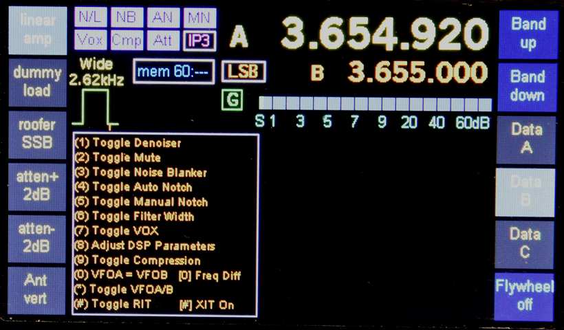
In this image, most touch
pads have been assigned to I2C devices.
Data A,B and C behave as
multually-exclusive buttons ('radio buttons') and the selected item is
is highlighted.
The atten+ and atten- buttons control a PA3AKE
attenuater (0,2,4...30dB).The atenuation displays
on the button.
The Flywheel buttons is DDS26. The button
caption changes between on and off as the
state toggles.
The button task on the Ant vert buttons is three-tasks to one-button
in a stepping mode. The button
caption changes as you step: Ant vert, Ant quad,
Ant G5RV. (All used definable in Hobcat)
The linear and dummy load buttons toggle on/off and highlight when on.
see I2C device control and PA3AKE
front end control.
DSP monitor
TRxAVR_picastar operates all the time with DSP parameter 5.2 = 2.
In this mode, DSP unit is continually
sending out serial telemetry containing 24 byte packets of data for the DSP
monitor and S meter.
This telemetry was intended for the DSP monitor in Picastar's PC based DSP monitor
provided in XJPld2g.bas.
With 320x240 graphics,
TrxAVR_picastar uses the same data
to provide its own DSP monitor display.
Eight signal level horizontal bars indicators are shown on
receive and on transmit.
Additionally, on receive, a gain bar is displayed to show receiver
gain distribution.
These DSP displays are closely modeled on the DSP monitor provided in XJPld2g.bas.
(Note that Hobcat also provides such a DSP monitor)
CAT
TrxAVR-Picastar provided remote CAT control
and monitoring using a dedicated two-wire serial RS232 port
operating at 38400 baud.
The Kenwood TS2000 command set is being used.
Initial operation was with the limited commands used by Commander 679
and Logger32.
I have now implemented 40 of the 106 Kenwood TS2000 commands, and tailored certain
aspects of the interface
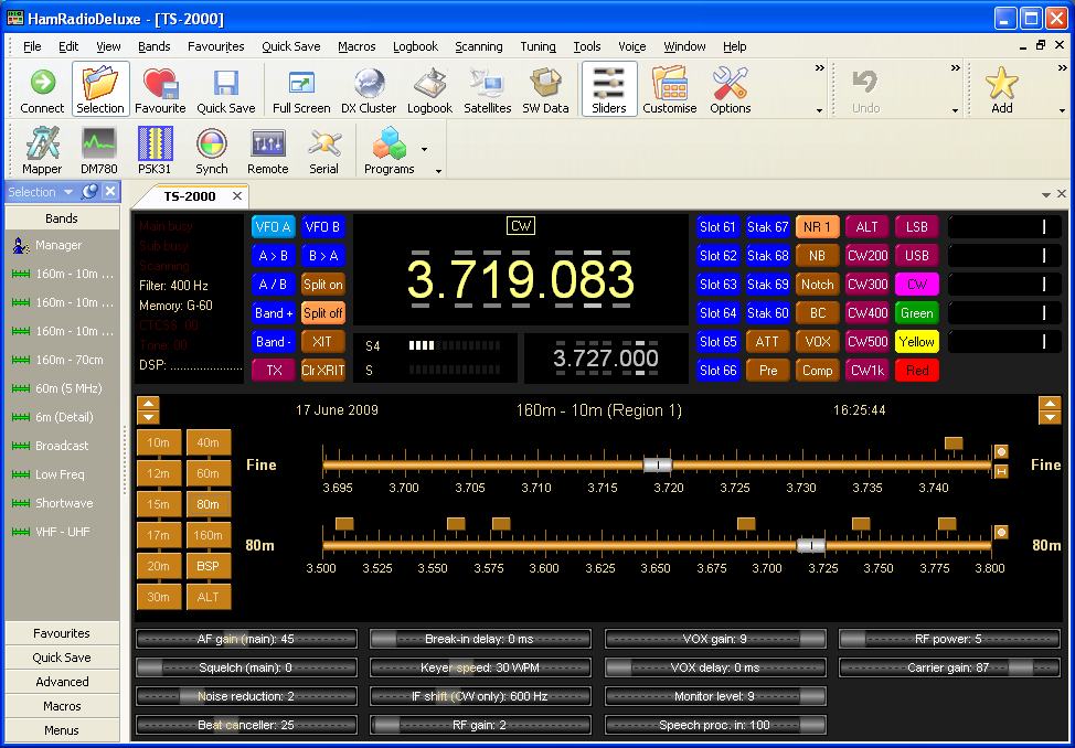
to work well with Ham Radio Deluxe. See CAT
and Download page .
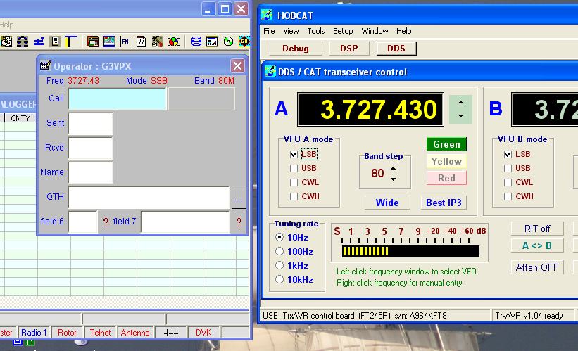
It is possible to operate both Hobcat and a serial
port application at the same time.
The screenshot below shows Looger32 used for logging and Hobcat for control.
The widow below shows Ham Radio Deluxe configured for TrxAVR-Picastar. (Use Right-mouse view-image)