The underside of the board is a ground plane and is soldered to the brass screening box.
TrxAVR-Picastar
- Preamp, 4xJ310amp and BPF switch for PA3AKE front end
Martein Bakker, PA3AKE has developed a superb HF transceiver front end.
It consists of:
A full description of the project is at:
http://www.xs4all.nl/~martein/pa3ake/hmode/index.html
These units are expensive to build but
probably represent the ultimate in performance.
They result from a large amount of experimental work.
For example:
- Martein's H-mode mixer development evaluated 13 transformer types and 7 different
Fairchild switches.
- He found that roofing filter crystals were a significant source of IMD and
so uses high specification crystals
from EQZAL.
- The BPFs for 160m - 20m use T94 toroids.
I quickly came to the conclusion that there
was no point in building this front end unless it closely followed Martein's
design. To do otherwise would make nonsense of the huge effort that is gone
in the optimising the design.
I have installed a PA3AKE BPF and H-mode
mixer / roofing filter unit in my TrxAVR Picastar rig.
A few others have done, or are doing or are considering doing the same.
Hobcat / Trxavr-Picastar has full software
support for the I2C controlled Pa3AKE units.
see PA3AKE software control
I have designed, built and documented three modules which are used in the PA3AKE installation:
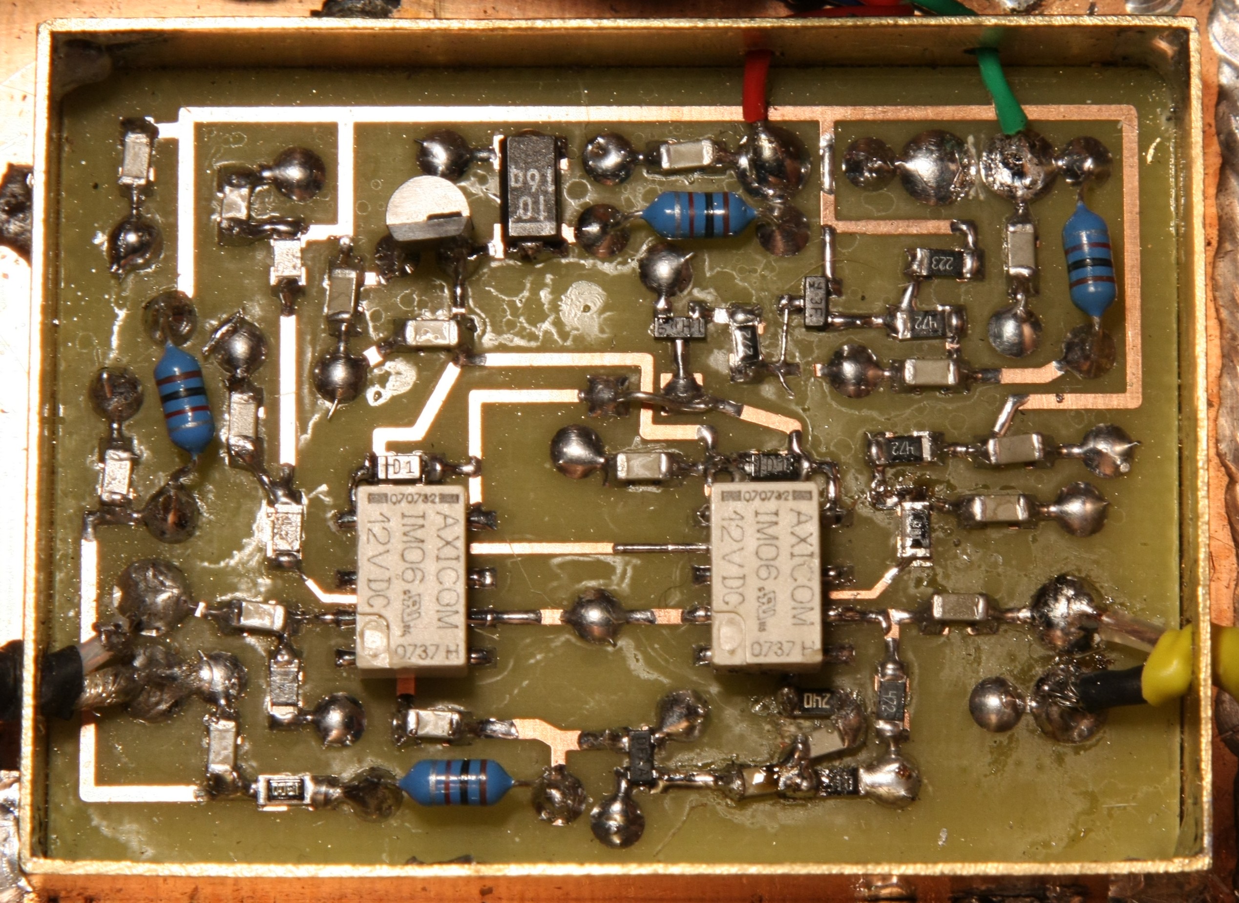
The PA3AKE BPF and roofing filter are switched
byAxicom IM06GR relays.
These are Farnell part no 1175070.
My policy in designing boards for this installation was:
PCB design
I have provided for each module: a schematic, a layout drawing and a mirrored
top side etching mask.
All the boards use the underside as a ground plane. Only the top needs etching.
No mounting hole positions are provided as I intended the PCBs to be soldered
into brass boxes.
However, mounting holes can be made if the board is made appropriately larger.
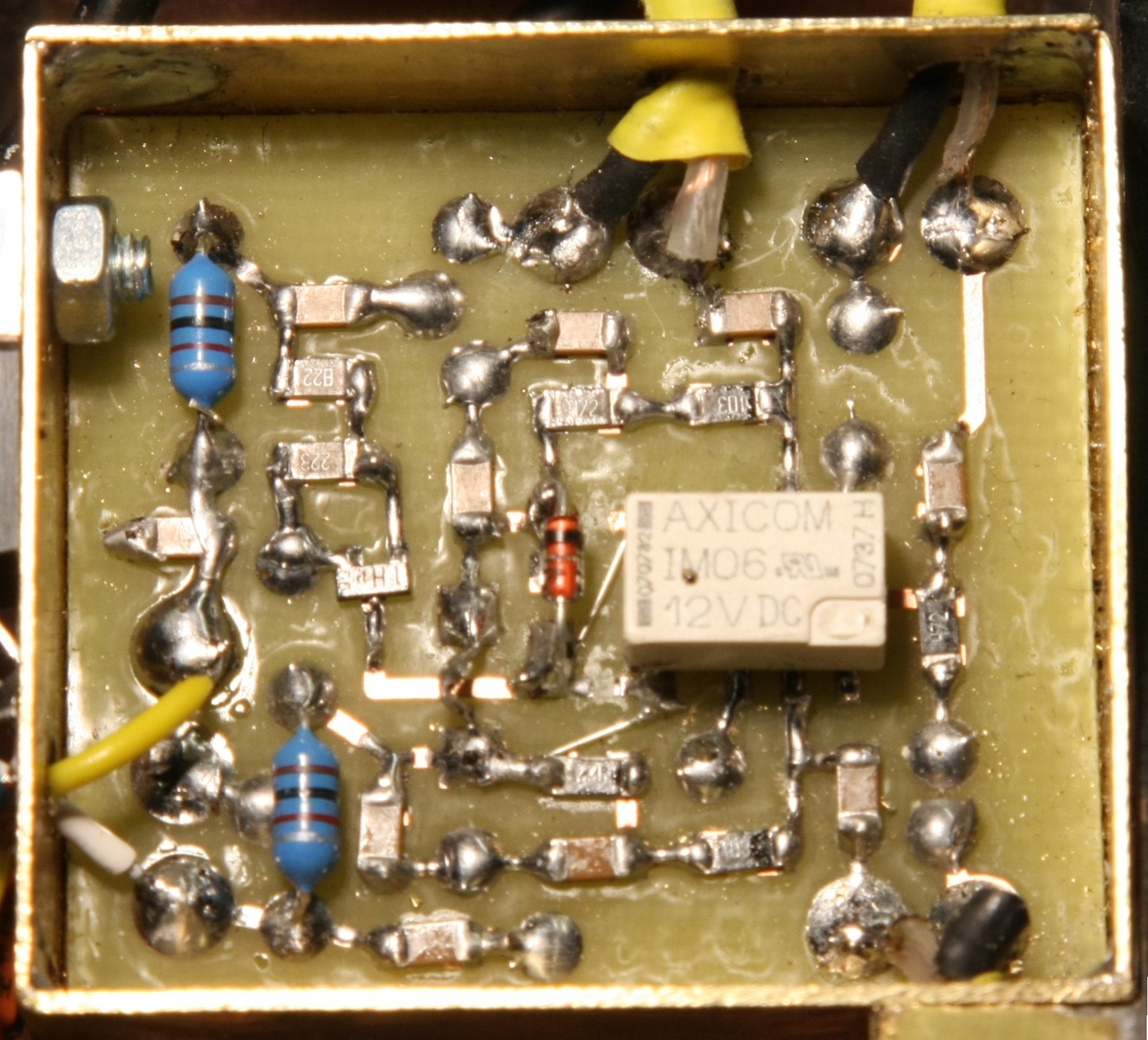
BPF switch
Switches the BPF 'input' between antenna
input (from the LPF unit) on receive and the PA input on tranmsit.
The underside of the board is a ground plane
and is soldered to the brass screening box.
BPF
switch schematic (pdf)
BPF switch layout (pdf)
BPF switch layout (pad2pad)
BPF switch top copper etch mask (mirrored)
4xJ310 amplifier
This amplifier is identical to that in the Picastar magic roundabout.
(see Picastar data for transformer details)
Directional switching is done by a FST3126 switch.
The amplifier IF port conencts to the birectional
J310 amplifier on the Picastar IF board.
The connection is to transformer T1.
The correct turns ratio for T1 is 3t:10t. (50ohm coax to approx
600ohm amplifier input)
4xJ310
amp schematic (pdf)
4xJ310 amp layout
(pdf)
4xJ310 amp layout
(pad2pad)
4xJ310 amp top
copper etch mask (mirrored)
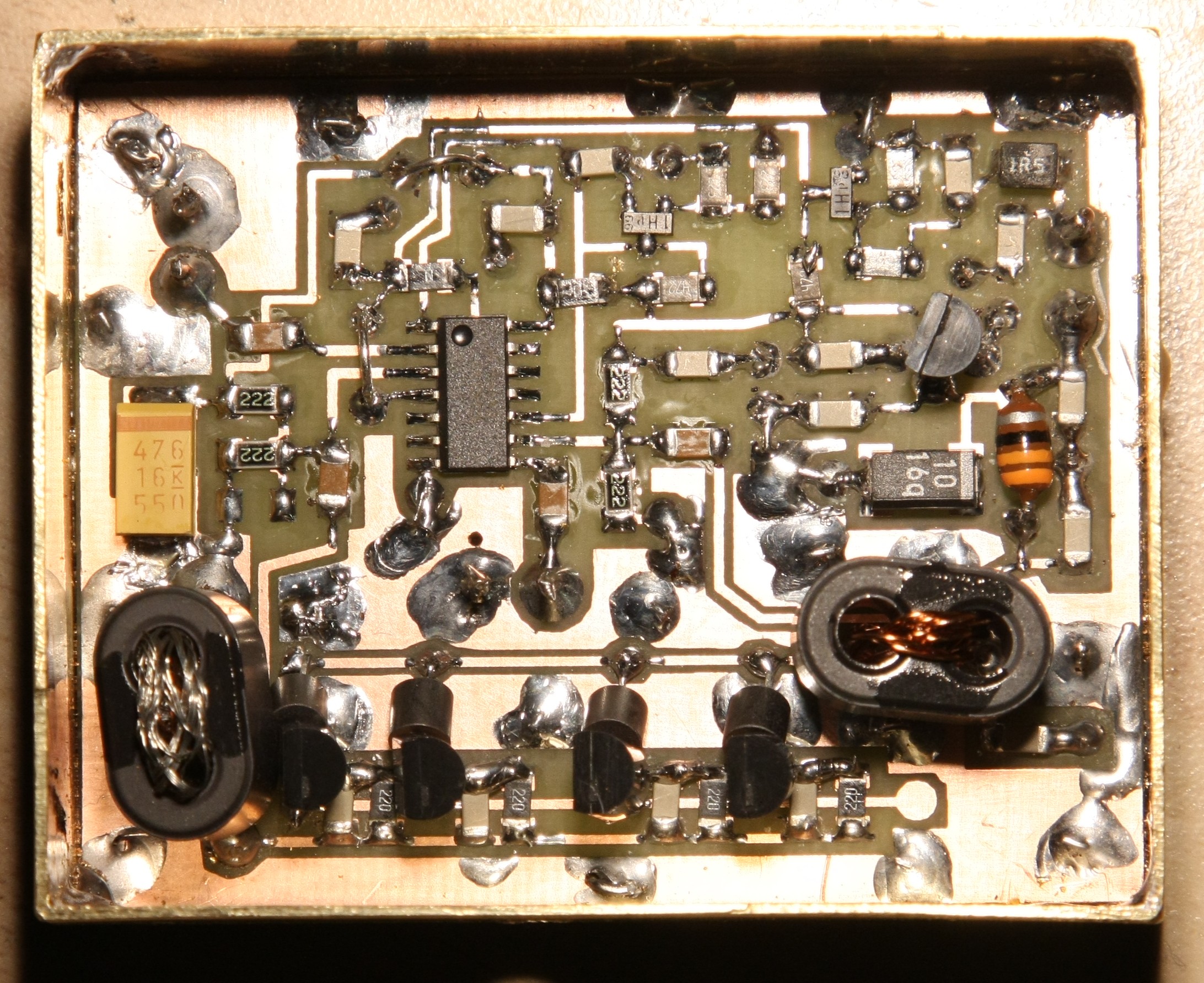
Pre amplifier
This uses a MAX2611 RF amplifier chip. See: http://datasheets.maxim-ic.com/en/ds/MAX2611.pdf
The IC has 19dB of gain. A 6dB input attenuator reduces the gain to 13dB.
The amplifier has to be switched out on
transmit.
In my rig it is controlled from one output a PCA9555 I2C chip and switched by
a touch button on the
colour TFT display panel. The Hobcat
/ TrxAVR system for control of a PCA9555 has provision for the
output to be optionally active only on receive. (this preamp mut be bypassed
on transmit)
See PCA9555 button tasks
This board is not quite the final layout. The 6dB (bottom right) attenuator
was added here as a modification.
preamp
schematic (pdf)
preamp layout
(pdf)
preamp layout
(pad2pad)
preamp top
copper etch mask (mirrored)