Hobcat Installation, Setup and Configuration
Hobcat source code and installation/ upgrades
- Hobcat installer download
- hobcatsetup.exe
- Hobcat internet update window
- hobcat_updates.htm
Hobcat
is written in Delphi 6 and uses developer addons: Raize components,
Express Quantum Grid suite, Embedded HTML help.
Recent source code is downloadable as: hobcat
source code (It will not compile without the Delphi addons!)
Installation uses Wise Installmaster 8.1. The installer program, HobcatSetup.exe is both an installer
and upgrader.
It does the following:
- Creates folder: Program files/hbradios/hobcat and installs hobcal.exe and help files
- Creates subfolder trxavrcode and installs the latest TrxAVR source code (zip file) and hex code.
- Creates subfolder encoders8 and installs the latest Encoders8 source code (zip file) and hex code.
- Creates subfolder hardware and installs schematics and layouts for the TrxAVR, Encoders8 and SwrBridge modules.
- Creates subfolder caldata for SwrBridge calibration data.
- Installs ft2dxx.dll in your \Windows\System32 folder
- Create registry entries, program-start menu entries and a desktop icon.
and then optionally downloads the latest hobcatsetup.exe. (.... has stopped working- under investigation!)
- Hobcat MOX control
- hobcat_mox.htm
- Hobcat database browser help
- database_browser_help.htm
- Hobcat database browser setup
- database_browser_setup.htm
Hobcat USB Interface
Hobcat was developed as a PC control, configuration and monitoring program for the TrxAVR_Picastar transceiver control board.
Communication with TxrAVR is via USB. TrxAVR uses a FT245R USB devicefrom FTDI (Future Technology
Devices International Ltd). This device and its supporting software provide a complete USB interface solution.
The device contains FIFO buffers, EEPROM, clock circuit and USB resistors.
FTDI provide PC drivers in the form of a dll (ftd2xx.dll). This dll is used
by:
- Mprog - A PC based EEPROM configuration utility (Download from: http://www.ftdichip.com/Resources/Utilities.htm#MProg
- Virtual COM port software to allow use of RS232 port software (not used by Hobcat)
- Demonstration source code in Delphi and C++
TrxAVR_Picastar Setup/configuration
Hobcat provides menu options for configuration of a TrxAVR-Picastar transceiver vai USB link.These are descibed in detail in the setup instructions:
Hobcat windows
Hobcat is written using a MDI (Multiple Document interface).
This allows several windows to open simultaneously (as with wordprocessor or
spreadsheet documents).
The open documents are listed in the Windows menu. The windows
may be shown one at a time, cascaded or tiled.
At present, Hobcat contains the following windows:
- Debug: This provides via USB background monitoring ofTxrAVR's Atmega2560 ports and selected internal variables.
It was developed early in order to facilitate TxrAVR code development and to establish working USB communication software. - DSP: this monitors and controls the Picastar DSP hardware. It mimics the Rx and Tx monitoring
display of G3XJP's loader.
It shows TrxAVRs rotary encoder assignments to DSP parameter control. (Encoders8) - DDS: This provides a dual VFO, CAT control interface via USB link.
Multiple Windows
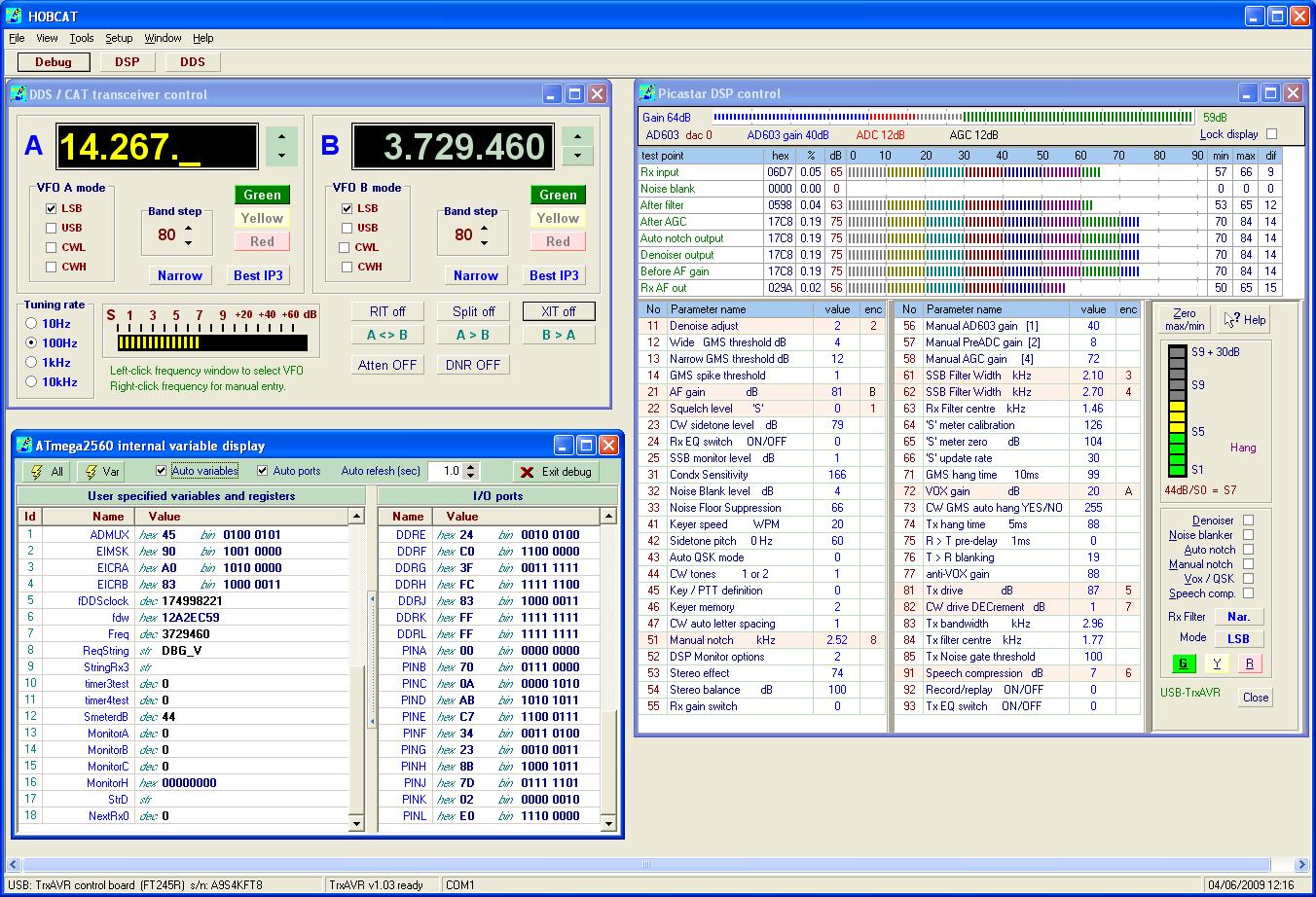
With a large resolution monitor, Hobcat can display mulitple monitoring and control windows.
Debug window
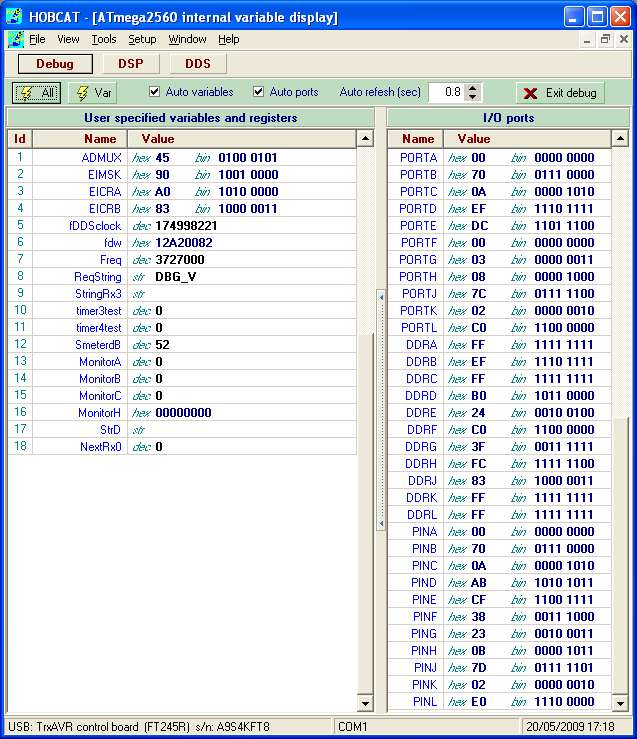
The toolbar controls provide for 'singleshot' or repetitive monitoring.
Each variable needs only single line of code adding to TxrAVR's taDebug.c module.
eg: result & = dbSendVar("EncoderTest[1]",(uint8_t*) &EncoderTest[1],'B','D');
This line of code includes the variable name as text and the formatting requirement (B = byte, D = decimal display)
- Thus no setting up is needed on the PC-based Hobcat program - It simply asks TxrAVR for the configured variables.
In the above display, the 9600baud messages from Encoders8 are controlling the values of the array of eight test variables, EncoderTest[0-7].
(The variable: StringRx0 shown above contains the latest Encoders8 output: $3+01 (which means encoder 3 increment by one)
The right pane has been dedicated for the PORT, DDR and PIN registers of the Atmega2560's eleven I/O ports.
Other Atmega2560 hardware registers can be optionally displayed in the left variables pane , eg: ADMUX, EIMSK etc as shown.
Hobcat's DDS window:
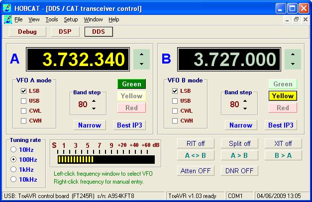
The A and B VFO windows display all the
data in the A and B Vfo slots.
Mouse control and some key board control is provided.
VFO A/B switching is by left-clicking the frequency display.
(Right-clicking the frequency display allows manual frequency entry)
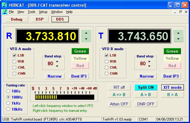
The above display shows XIT - selected
by a long pressof # on the transceiever or by the XIT button.
Split is on initially by default, as in Picastar.
VFOs are labelled R and T as in TrxAVR-Picastar and VOF frequencies are initially
that or the previous active VFO.
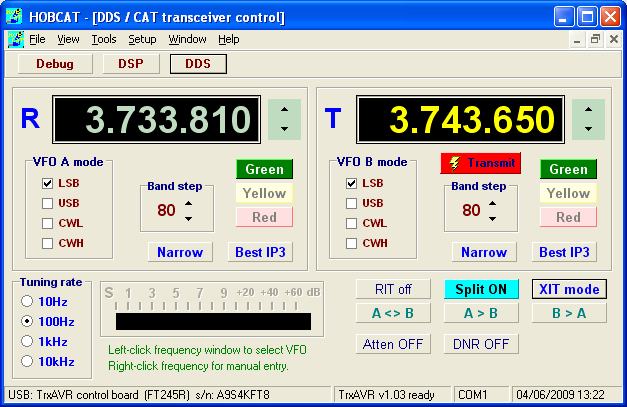
On transmit, the transmit VFO show as active (yellow digits) and has a transmit indicator.
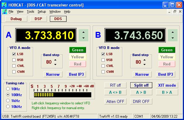
Clicking the Split button switches Split off but maintains XIT mode. With Split off, transmit frequency is that of VFO A
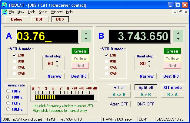
VFO A freqeuncy window has been right-clicked
to allow manual frequency entry.
(The backspace and ESC keys are supported)
MOX button
(manual
T/R switching)
Version 1.055 added a MOX button to the DDS window. See: Hobcat
MOX
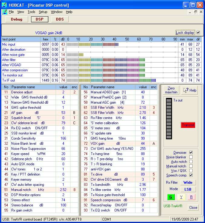
Hobcats DSP window:
Hobcat's DSP display on receive is shown below:
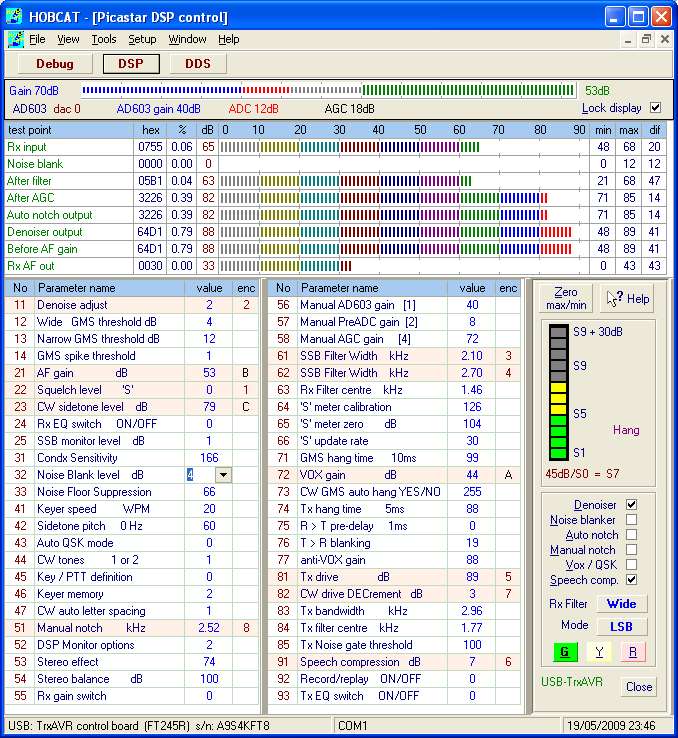
The parameter names and max, min and multiplier are from User2b2.xjp, but the data is from TrxAVR.
The parameter list EXCLUDES those parameters whose name in Use2b2.xjp is preceded
by an 'x'. This is hard coded in TrxAVR-Picastar.
These locked parameters were optimised by G3XJP when Picastar development ended
in September 2008 and should not need to be changed.
(They could in fact be changed in User2b2.xjp and then transmitted to TrxAVR....
this is seriously not recommended .... hence no access to them
in Hobcat / TrxAVR)
Note the yellow edit
box. Clicking on the Noise blank level cell displays the grey down arrow.
A further click on this arrow displays the yellow spin edit box which allows the volume
to be adjusted. TrxAVR_Picastar responds
as you adjust it.. and the value is stored in EEPROM). A final click away from
the edit box completes the edit.
The bottom right controls display the status of the corresponding TrxAVR switches
and also provide PC control of these switches.
The G, Y and R buttons will switch parameter sets on TrxAVR-Picastar.
The enc column shows the assignment TrxAVR's rotary encoders and potentiomters
to parameter control (see Encoders8).
TrxAVR supports upto eight encoders (labelled 1 to 8) and two patentiomters
(labelled A and B). The assignment of these is made in TrxAVR.
The analogue pots are easy to connect but are of somewhat limited use as the
parameter assumes the pot-defined value as soon as assigned.
Volume (2.1) is the most obvious use, and is modified to range 50-100 (rather
than 0-100). The full ADC range of 0-1023 might not be achieved
and so the parameter range is controlled by ADC range 100-960. (ie the parameter
control uses approx. 85% of the pot's rotation)
Note that when you control the DSP with Hobcat, you are communicating with the DSP through
TrxAVR which converts the USB commands into serial telemetry to the DSP. The adjustments that you make are stored in
TrxAVR's 24LC512 EEPROM and so are retained on power down/up.
However, if DDS39 = parameter-reset-mode is on, all parameters will be set to
default backup values on startup.
TrxAVR-Picastar operates with parameter 5.2 set to 2. This provides for simultaneous internal (S-meter, graphic DSP display) and external (Hobcat) monitoring.
I was able to confirm the correct operating of this DSP display by running Hobcat's DSP display (via USB) and G3XJP's DSP monitor display (via RS232) alongside each other in the PC screen.
Data
route:
The DSP unit has two-way 9600 baud telemetry with UART2 of TrxAVR's ATmega2560 controller.
This is routed through a 3.5mm jack socket which allows standard Picastar communication
via serial link.
This is used by G3XJP's test and IF clalibration programs. (and some G3XJP loader
functions if you wish)
Hobcat's DSP display on transmit:
Coding:
Hobcat is written using Borland Delphi 6 with addon software:
Raize components
These provide enhanced versions of standard windows controls, eg: flat buttons. The LED bar indicator is also due to Raize.
Developer Express Quantum Grid Suite
This provides a superb
set of components for data-aware grid and tree list development.
(superb = great effects from minimal coding!!)
There are four instances of their TdxDbgrid on the DSP window. The uppermost is
the gain bar which is a grid with one row, one (visible) column and no header!
The grids are designed to display data from remote database datasets using SQL
quereies. ( You can in fact do live editing of database tables accross the internet)
In Hobcat there is no database. However, DE provide a very useful TMEMdata component
which is descendant of Deplhi's TDataSet component which is the common ancestor
of various database access components. TMemdata has database-like fields. You
link it to the grid, create some fields corresponding to the grid columns and
then populate and add records, one for each grid row. TMEMdata is thus a tempory
memory based database.
The meter bars and calibration markings are produced by intercepting the cell
drawing message and drawing lines and rectangles. DE make it relatively easy:
One mouse click creates a skeleton cell-owner-draw intercept routine with column
number, row number, cell coordinates, cell drawing canvas etc etc all provided
as parameters. (This routine will be called every time the cell is redrawn ..
ie: on data upadates - but also .. repetitively .. when you move the window
or drag something across it..... all this is taken care of .. I dont have to
do it))
Below is part of the cell owner -draw routine for the cell with eight abr meters:
// The following parameter provided automatically are used here:
- // ACanvas
- - the drawing object with lines, rectangles, brushes, pens, drawing routiens etc
- // ARect
- - a rectangle (left, top, right and bottom) which defines the grid cell that we are drawing
- // ANode
- - the current mode (= grid row) -whose field values contain the data
- // AColumn
- - the current grid column
- // ADone
- - a true/false variable. We are in a interception before the start of the built-in default cell drawing routine
// In other situations, this owner draw facitily might just change a colour or font style for the cell (using AFont)
//and so ADone is not set as we want the default routine to draw the text but with our font changes.
begin
Pen.Style := psSolid; // Pen is a property of ACanvas
Pen.Mode := pmCopy;
Pen.Color := dxDBGrid_Meter.GridLineColor; // defined in a property editor table
Pen.Width := 1;
if AColumn = MCol_Meter then // if we drawing the meter-bar cell
begin
FillRect(ARect); // Blan teh cell. ARect has screen coordinates of the cells corners
for i := 1 to 9 do // we are dividing the 90dB bar into 9 x 10 blobs
begin
MoveTo(x,Top); // go to the top at this X position
LineTo(x,Top+2); // draw downwards a three pixel calibration line
MoveTo(x,Bottom-2); //go to cell bottom at this X position
LineTo(x,Bottom); // draw upwards a three pixel calibration line
BarRect.Bottom := Bottom-3; //bottom of BarRect is 3px above the bottom of cell
for i := 1 to dbpeak do // we will draw one bar for every dB
begin
BarRect.Right := Left+i*4; // x coord = left of cell + 4 x dBs ( so 3 pixels wide)
Brush.Color := BarColours[(i-1) DIV 10]; // we already have table of nine colour codes
FillRect(BarRect); // draw the rectangular blob using BarRect coords, and Brush.color
ADone := true; // Block the subsequent built-in default cell drawing routine